• The move to the new server is done. There are some software and database maintenance updates in process. This has us passing the hat around to help out. We appreciate any donations. Seriously, even a dollar helps. The payment page may be found here - https://www.audiokarma.org/support.html

Fix that Sansui 9090db with a Bad db board

"Did you check the power supply"

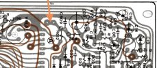
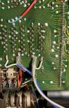
Hi, I wasn't sure if this was a question, or part of your signature (as I couldn't quote it LOL), but it's a good question - to power down the bypassed Dolby board F-2655 this wire needs to be removed, which is the power feed to the board.

Once removed, I'm not really sure of a neat place to put it, perhaps simply just cutting the track next to it is the neatest answer, or just insulate the end and tie it up so it doesn't wander around and touch something :D
 

Attachments

  • Power connection to F-2655.jpg
    Power connection to F-2655.jpg
    116.3 KB · Views: 55
Interesting, it doesn't quite agree with the schematic I have here, but like you say, it's a big improvement.
From looking at the actual physical F-2654 switch board, you should be able to trace the route to confirm the tape monitors and that the channels don't get swapped over - Tape Monitor 2 is switched around for ease of PCB layout,

Basically the (newly soldered to pins 1 and 2) input from the receiver selector goes into the end switches of the Tape monitor 1 switch, and out to TR1 (Tape Record 1) RCAs on the back. The TP1 (Tape Play 1 goes into the very end of that Tape Monitor 1 switch, and the 2nd row in is the selection - Monitor the Tape 1, or listen to the receiver selected input.

They feed up to pin 7 and 8 of the ribbon strip, so are jumpered to pin 11 and 12 of that strip to head to Tape Monitor 2 switch, RCA sockets etc.
The result of Tape Monitor 2 then arrives on ribbon pins 19 and 20, and are jumpered to 23 and 24 which is essentially the route out of the F-2654 board.

So this path can be traced and buzzed out so you can see and test the bypass, before reassembly :)
 
Last edited:
Sansui 9090DB Dolby board component list???
I got the new Dolby board, very nice quality, switching over all the old components to the new board. the service manual doesn't a component list
I've got all new caps, transistors, pots, installed not sure about some of the other components, anyone have a parts list for this board? Thx.
 
Open the Excel spreadsheet included in the zip archive for the board files, and check the PCB Specs tab.
Column A is the reference designator, and column E has the component values.
Scroll down farther and there is a "Mechanical Specs" section with more info on size and lead spacing.
 
Last edited:
Open the Excel spreadsheet included in the zip archive for the board files, and check the PCB Specs tab.
Column A is the reference designator, and column E has the component values.
Scroll down farther and there is a "Mechanical Specs" section with more info on size and lead spacing.
I appreciate the info for the component list but I can't locate the board files section. I tried searching all over. Can you point me in the right direction? Thx
 
I appreciate the info for the component list but I can't locate the board files section. I tried searching all over. Can you point me in the right direction? Thx

Here's the direct link to the zip: (link)

Also, member BradWil is currently in the middle of building a BOM, you might want to keep an eye on the original thread I posted: (link)
 
Hi all, I looked at this issue recently as I have an 8080DB (although that works fine), and it was a bit of a 'puzzle challenge' :)

I looked at the schematics, the F-2655 board already has a bypass function, position 3 on the dolby selector knob.
If that doesn't perfectly bypass it, then there is a fault with either the selector switch (the signal goes through it 3 times) or the ribbon wires have cracked, or the tape monitor 1 or 2 are faulty. Or a combination.

As for the actual bypass, if for some reason cleaning the switch or replacing the ribbon is not the favoured approach - it can be fairly easily bypassed from the parent F-2654 board, without touching the F-2655 board, that can stay in there safely preserved.

The pin numbering of the ribbon is amusingly 'non-sequential', and the service manual has some errors, which may make the task of computing a bypass seem tricky, but once the correct S01 switch elements are identified, along with the correct ribbon pins, the task is straightforward.

- Simply remove all the ribbons, then on the F-2654 use 4 jumper wires in place of the ribbon (to emulate the dolby 'off' position), and then unsolder the f/g blue and grey signal input wires from the F-2655 daughter board, and solder them instead straight to the F-2654 board.
That's it.

ETA:
If you look carefully at my attached image, you can trace the signal as it arrives at pins 1 and 2, into the Tape Record out 1 (TR1) and Tape Monitor 1 switch, the switch selects source or Tape Play 1 (TP1), then goes to TR2 and tape monitor 2 switch for TP2, then via pins 23 and 24 goes to the mono, loudness etc and then out of 33 and 34 to the tone board.
I.e. my bypass method here is simple and gives the full tape loop functionality of the original.
I.e. this is the solution everyone has been looking for :)

Doing this, (in theory, I've not done this to mine as it works), gives the behaviour of 'dolby Off', without any signal touching the F-2655 board.
I post the image I made as I worked it out for anyone who is interested - I don't think bypassing is the best fix, but at least my method preserves the F-2655 board for the future, and allows the tape loops to work as in the original) so it's Ok I guess :D

If anyone does this bypass, please post up how it works for them :)

I just performed this bypass on an 8080DB and it works as advertised. It completely eliminates the Dolby board and maintains the tape functions. The Dolby board is completely disconnected, no wires attached. I've installed it back in the chassis so it's rotary switch and pots fill the holes in the face plate but they have no function at all.

To relocate the shielded Gray and Blue shielded inputs, the ground for the shields needs to be extended. In my case, I also had to do some therapy on the tiny traces on the push switch board. They lift and break so easily.

This 8080DB has a history of Dolby issues. I've been messing with it for years. Originally it had failed diodes and other components on the Dolby board. I completely rebuilt it, pinning all the pass throughs but never completely eliminated random channel drop out. I was faced with having to redo it. With the bypass, it's singing out of both channels and the tape functions work. Thank you for solving this vexing problem.

- Pete
 
I think I’m misunderstanding what was written in post #34:
…I looked at the schematics, the F-2655 board already has a bypass function, position 3 on the dolby selector knob.
If that doesn't perfectly bypass it, then there is a fault with either the selector switch (the signal goes through it 3 times) or the ribbon wires have cracked, or the tape monitor 1 or 2 are faulty. Or a combination….
if the dolby switch is set to “off”, the dolby board is already bypassed? Assuming there is no faults in the other circuits/wiring external to the dolby board?

Wouldn’t that eliminate the need to repin/reflow the dolby board if the sound fails?

I must be not understanding that fully. If that is the case, then all these guys have been reworking dolby boards all these years when they didn’t have to?

Something is just not tracking there for me. Not trying to call anyone out, I’m just trying to understand the workings going on in there.

Its more just me being curious than anything else as my 8080db board hasn’t caused me any issues. But I also do keep the dolby selector in the off position so maybe I just don’t know theres an issue? At least I’ve never noticed any problems on the other positions when/if I rotate through them…
 
Last edited:
I think I’m misunderstanding what was written in post #34:

if the dolby switch is set to “off”, the dolby board is already bypassed? Assuming there is no faults in the other circuits/wiring external to the dolby board?

Wouldn’t that eliminate the need to repin/reflow the dolby board if the sound fails?

I must be not understanding that fully. If that is the case, then all these guys have been reworking dolby boards all these years when they didn’t have to?
What you posted is true if "position 3" is the "Off" position on the Dolby panel.
If you have no problems with your 9090db and don't plan on utilizing the Dolby function, then there's no reason to rework the board. However, some have had issues with the Dolby switch in the "Off" position and some just want to eliminate the chance of the Dolby board ever becoming an issue. So performing the bypass scratches that itch and leaves the tape functions intact.
 
What you posted is true if "position 3" is the "Off" position on the Dolby panel.
If you have no problems with your 9090db and don't plan on utilizing the Dolby function, then there's no reason to rework the board. However, some have had issues with the Dolby switch in the "Off" position and some just want to eliminate the chance of the Dolby board ever becoming an issue. So performing the bypass scratches that itch and leaves the tape functions intact.
That's kind of what I'm trying to understand. If there's problems with sound and the Dobly board is bypassed in the "OFF" position, how is the board itself the problem and if re-pinning/reflowing fixes the problem, doesn't that indicate the "off" position doesn't actually bypass the dolby board?

I'm just looking at this logically. Although I can read a wiring diagram well enough, the circuit topography/design is above my pay grade....
 
That's kind of what I'm trying to understand. If there's problems with sound and the Dobly board is bypassed in the "OFF" position, how is the board itself the problem and if re-pinning/reflowing fixes the problem, doesn't that indicate the "off" position doesn't actually bypass the dolby board?

I'm just looking at this logically. Although I can read a wiring diagram well enough, the circuit topography/design is above my pay grade....
I don't have the schematic but I see what you mean, as Globulator's post states there is a fault with either the selector switch, the ribbon wires, the tape monitors or a combination of those are faulty. This would mean cleaning the switch or replacing the ribbon should fix the issue. The exercise of re-pinning the board would serve no purpose, unless you wanted the board to be functional.
 
I don't have the schematic but I see what you mean, as Globulator's post states there is a fault with either the selector switch, the ribbon wires, the tape monitors or a combination of those are faulty. This would mean cleaning the switch or replacing the ribbon should fix the issue. The exercise of re-pinning the board would serve no purpose, unless you wanted the board to be functional.
Thats what I’m thinking it means. Dolby being a “dead” format, I would think someone would avoid the trouble of re-pinning (or bypassing for that matter) and just turn the dobly off…if off is indeed a stright up bypass.

fixing a ribbon cable or cleaning a selector seems easier too…
 
Thats what I’m thinking it means. Dolby being a “dead” format, I would think someone would avoid the trouble of re-pinning (or bypassing for that matter) and just turn the dobly off…if off is indeed a stright up bypass.

fixing a ribbon cable or cleaning a selector seems easier too…
True, but I know I wanted my board to be completely functional, even though I would never use it. Some buyers are OCD about having everything functional and expect a discount on their purchase, even though they'll never use the Dolby function. So I made sure all my receivers had functioning Dolby before selling them.
But if the owner plans on it being his forever receiver, then he can do what he wants with it.
 
Fair enough. If selling stuff, you don’t want any room for the buyer to go “yeah, but…” when discussing cash.


But I’m still wondering if its actually true that the “Off” position will just bypass a bad board and recover any sound issues…assuming no other faults in the unit.
 
Working on a March 1978 9090DB. It's in excellent condition but is eluding an easy fix.
The audio signal is there but is very faint with some other oddities as mentioned regarding signal and button functions. There is also a 'hum'' present in the observed audio signal - but the volume is all the way up.
Buttons on F-2654 Push Switch Circuit Board
Loudness doesn't seem to work
Mono seems to work
FM muting I did not test
Tape 1 & 2 function was confused because an imported signal was everywhere due to crosstalk.
Dolby test function was non-existent.

To do the above discussed bypass
:
To remove the ribbon as suggested - Remove ribbon from Switch Board F-2654 or Dolby Board F-2655 or does it matter?
I assume the gray and blue wires to the Dolby Board the ones in the image I've attached?
Are the white wires on each gray and blue wire the ground wires and these white wires are then rerouted to the green ground position pictured?
Am I correct that the blue wire goes to position '1'
Is the Gray wire represented as the Red wire and goes to position '2'
Which one (gray, blue, red) right channel or left?

Thanks Folks
 

Attachments

  • Gray-Blue-White to F2655 Dolby Board.jpg
    Gray-Blue-White to F2655 Dolby Board.jpg
    161.3 KB · Views: 43
  • By-Pass Dolby Board.png
    By-Pass Dolby Board.png
    693.6 KB · Views: 46
@tourmax, to my knowledge, setting the rotary switch to OFF turns off the Dolby function but all the inputs and outputs still go through the Dolby Board. When set in the Off position, the switch "bypasses" the Dolby functions connecting the inputs to the Dolby board to the Output from the Dolby board. There are still pass throughs in those circuits so even when set to OFF, you can still have dropout caused by intermittent pass throughs. I believe @Globulator reverse engineered the OFF position to come up with his excellent bypass. It completely eliminates the Dolby board.

Working on a March 1978 9090DB. It's in excellent condition but is eluding an easy fix.
The audio signal is there but is very faint with some other oddities as mentioned regarding signal and button functions. There is also a 'hum'' present in the observed audio signal - but the volume is all the way up.
Buttons on F-2654 Push Switch Circuit Board
Loudness doesn't seem to work
Mono seems to work
FM muting I did not test
Tape 1 & 2 function was confused because an imported signal was everywhere due to crosstalk.
Dolby test function was non-existent.

To do the above discussed bypass:
To remove the ribbon as suggested - Remove ribbon from Switch Board F-2654 or Dolby Board F-2655 or does it matter?
I assume the gray and blue wires to the Dolby Board the ones in the image I've attached?
Are the white wires on each gray and blue wire the ground wires and these white wires are then rerouted to the green ground position pictured?
Am I correct that the blue wire goes to position '1'
Is the Gray wire represented as the Red wire and goes to position '2'
Which one (gray, blue, red) right channel or left?

Thanks Folks

Remove the ribbon cable from both the Dolby board AND the push switch board. The jumpers are all installed on the push switch board in the indicated holes formerly used by the ribbon cable. When you are done with this bypass, the Dolby board is completely disconnected. You can just clip off the loose yellow and black wires. You don't have to install it at all except without it, there will be open holes in the face plate.

He used red and blue to indicate the left and right channels continuing the Sansui format for the gray wires and blue signal wires. The white wire in each of shielded signal wires, is the wire carrying the signal. They go to pins one and two. Blue to one and Gray (red) to two. The other mesh wire is the ground. You will need to extend the ground wires to reach the indicated ground point on the push switch board.

The 8080DB I did last week is playing flawlessly every day in my kitchen. It's on right now as I type this.

- Pete
 
@tourmax, to my knowledge, setting the rotary switch to OFF turns off the Dolby function but all the inputs and outputs still go through the Dolby Board. When set in the Off position, the switch "bypasses" the Dolby functions connecting the inputs to the Dolby board to the Output from the Dolby board. There are still pass throughs in those circuits so even when set to OFF, you can still have dropout caused by intermittent pass throughs. I believe @Globulator reverse engineered the OFF position to come up with his excellent bypass. It completely eliminates the Dolby board.

.

- Pete
Ah, that at least makes sense. Thanks for “de-conflicting” my brain!

I think I’ll save glob’s writeup and pictures to a word doc, print it off and put it in (what I call) my “big book of stereo” in the 8080DB SM/info section.

My 8080DB is a sept 78 build by the ser number (black cables, riveted passthroughs, etc) and while my DB hasn’t given me any troubles to date, you just never know what the future may hold for 45-50 year old electronics ….;)
 
Last edited:
I still think that to properly restore an X0X0 DB model, the Dolby function should be restored, not bypassed. That was my original intent with the 8080DB I just bypassed. I went the bypass route because this particular Dolby board had serious issues to begin with. I had to replace a number of the geranium diodes and I was never certain about the quality of the no name geranium diodes I bought to replace them. I've successfully pinned several Dolby boards but this one continued to have intermittent drop out issues. It sat on my bench open for years and I would fiddle with when I was in the mood. The board had been reworked so many times that more manipulation could cause as many issues as it solved. So I used the nuclear option and just bypassed the damn thing.

- Pete
 
Back
Top Bottom