

You are using an out of date browser. It may not display this or other websites correctly.
You should upgrade or use an alternative browser.
You should upgrade or use an alternative browser.
I think I found the ultimate indoor antenna
- Thread starter z-adamson
- Start date


Wow! Is that a color organ? Haven't seen one of those since the 70's. (I love it.)
View attachment 1571503

Yes it is a color organ...
I built it myself, cabinet and electronics, back in the 70's based on a schematic from a magazine. Designed and etched a circuit board for it.
Still works... Never use it, but can't bring myself to toss it.
It also has outlets in the back for additional lights. Back then I had it connected to colored lights installed behind plastic panels in my basement ceiling.


loopstick
Lunatic Member
Not necessarily. Rabbit ears are infinitely configurable. I used them at the office to pluck a weak college station out of a shitstorm of computer noise.Better than rabbit ears...


USA Soccer
Well-Known Member
I have one and I love it.

Freds.Bands
Live Music Listener
The Terk passive indoor antenna is being delivered today. We’ll see how it works with my Sony HD tuner.
Despite what they say, it is directional; go for the antenna preamp.

Hak Foo
Active Member
I recall years ago various "As Seen On TV"/"As seen in Parade magazine inserted into the newspaper" products which professed to plug into the wall and use the mains wiring as an antenna. While targered towards TV, has anyone 1) seen one in the last 30 years and 2) tried it for FM? I'm suspecting the promise was that the size of the antenna compensated for being not targeted to any specific desirable frequency.

amptramp
Well-Known Member
I recall years ago various "As Seen On TV"/"As seen in Parade magazine inserted into the newspaper" products which professed to plug into the wall and use the mains wiring as an antenna. While targered towards TV, has anyone 1) seen one in the last 30 years and 2) tried it for FM? I'm suspecting the promise was that the size of the antenna compensated for being not targeted to any specific desirable frequency.
A lot of early FM tube radios had a choke on the input power lead and a small capacitor going from the power line side of the choke to the input of the RF amplifier. The power line antenna was the standard antenna that was usually connected by a jumper but could be disconnected to add an external antenna.

yofi
Well-Known Member
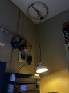
My wife thinks this is ridiculous, which is why it’s in my office.
I don’t have any access to the roof, and I am on the fence about whether I should start drilling holes in the property manager’s ceiling for attic mounting. But I’ve tried a few different kinds of antenna and this is the best solution so far. I’m trying to pull from two, opposite directions, about twenty miles distant from each source. This flying saucer thingie does the trick.

k6sti
Active Member
I’m trying to pull from two, opposite directions
A properly oriented dipole in the same location will yield higher signal levels, but the increase may not be enough to matter.
These circular "omnidirectional" antennas are not omnidirectional across the FM band (if they are omnidirectional at all). If reception is marginal for a particular station, try rotating the antenna.
Brian
P.S. I had the crossed-dipole type of omni in mind when I commented on the response across the band. I don't know how this antenna behaves. But here's a pattern from the datasheet:
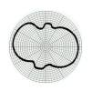
The scale and frequency are unspecified.
Gain is listed as 4 dB. Over what is not stated. I wonder if they mean to imply over your current antenna.
I would definitely try rotating this antenna for best reception on the station you're have the most trouble receiving.
Last edited:
yofi
Well-Known Member
I hung it by three hooks in order to be able to rotate it.A properly oriented dipole in the same location will yield higher signal levels, but the increase may not be enough to matter.
These circular "omnidirectional" antennas are not omnidirectional across the FM band (if they are omnidirectional at all). If reception is marginal for a particular station, try rotating the antenna.
Brian
P.S. I had the crossed-dipole type of omni in mind when I commented on the response across the band. I don't know how this antenna behaves. But here's a pattern from the datasheet:
View attachment 3824465
The scale and frequency are unspecified.
Gain is listed as 4 dB. Over what is not stated. I wonder if they mean to imply over your current antenna.
I would definitely try rotating this antenna for best reception on the station you're have the most trouble receiving.

Just got one of those myself. seems to work quite well, although my wife wasn't a huge fan when she saw it in my office.Every FM station comes in chrystal clear, stereo and mono.
I get stations I didn't used to get at all with my 6ft long dipole T style antenna.
Very impressed.
And for a whole 20 dollars. Can't beat it.
View attachment 1449541

So I moved it upstairs to the electronics lab


dinger
Active Member
Do you think you could model this antenna and add it to the 88-108 Mhz Library?A properly oriented dipole in the same location will yield higher signal levels, but the increase may not be enough to matter.
These circular "omnidirectional" antennas are not omnidirectional across the FM band (if they are omnidirectional at all). If reception is marginal for a particular station, try rotating the antenna.
Brian
P.S. I had the crossed-dipole type of omni in mind when I commented on the response across the band. I don't know how this antenna behaves. But here's a pattern from the datasheet:
View attachment 3824465
The scale and frequency are unspecified.
Gain is listed as 4 dB. Over what is not stated. I wonder if they mean to imply over your current antenna.
I would definitely try rotating this antenna for best reception on the station you're have the most trouble receiving.
k6sti
Active Member
Do you think you could model this antenna and add it to the 88-108 Mhz Library?
Accurately modeling this antenna would require a fair amount of effort. It's hard to develop any motivation since I don't think much of the design. The antenna's only virtue is that it is already assembled. Its performance is inferior to several designs that anyone can easily build. Even a lowly folded dipole that used to be included with every tuner can provide stronger signals. Orienting the dipole vertically makes it omnidirectional, if that's what you need. I think I'll let the meaningless gain figure and pattern from the datasheet speak for themselves.
Brian
P.S. I forgot about the antenna's other virtue: it is compact.
Last edited:
dinger
Active Member
I get it. I looked at the mfg's site and saw the same graphic with no numbers attached to it. This is surely not marketed to be taken seriously. I do think it's possible this antenna punches above it's weight even if by accident. I have 4 or 5 cluttering up my attic spaces and happy with the results. This brings up a long standing pet peeve I have: The 50 ohm crowd has all the cool and high quality gear they could even need while us 75 ohmers have to make do with mostly crap unless DIY.
k6sti
Active Member
I do think it's possible this antenna punches above it's weight even if by accident.
How would that be possible? By what mechanism? Antennas behave according to well-defined rules. The rules are mathematical, which allows their performance to be calculated. An antenna won't have unexpected performance if it's been properly characterized. There is nothing mysterious about them.
This particular antenna is nothing more than a folded dipole bent into a circle. To the extent it is more omnidirectional than the dipole, it has less gain in its most favorable direction and will deliver a lower signal level. You can determine that much without any further information.
One thing to note is that this antenna has dielectric at the high-impedance dipole ends. This is just where you don't want it. I don't know how lossy the dielectric is, but this antenna is just asking for trouble. Here's an example of what can happen when ice forms on dipole ends:
Vertically Polarized Yagi Stack
Brian

Still a folded dipole wrapped around itself and I can't see how or where it can have much real gain in this configuration... maybe -3DBd?


