• The move to the new server is done. There are some software and database maintenance updates in process. This has us passing the hat around to help out. We appreciate any donations. Seriously, even a dollar helps. The payment page may be found here - https://www.audiokarma.org/support.html

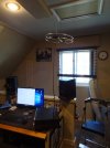
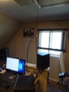
I think I found the ultimate indoor antenna

3823745


My wife thinks this is ridiculous, which is why it’s in my office.

I don’t have any access to the roof, and I am on the fence about whether I should start drilling holes in the property manager’s ceiling for attic mounting. But I’ve tried a few different kinds of antenna and this is the best solution so far. I’m trying to pull from two, opposite directions, about twenty miles distant from each source. This flying saucer thingie does the trick.

It looks a bit like an alien invasion. If you hear “we mean no harm to your planet” coming out of your radio ——- run!!! :):)
 
Last edited:
How would that be possible? By what mechanism? Antennas behave according to well-defined rules. The rules are mathematical, which allows their performance to be calculated. An antenna won't have unexpected performance if it's been properly characterized. There is nothing mysterious about them.

This particular antenna is nothing more than a folded dipole bent into a circle. To the extent it is more omnidirectional than the dipole, it has less gain in its most favorable direction and will deliver a lower signal level. You can determine that much without any further information.

One thing to note is that this antenna has dielectric at the high-impedance dipole ends. This is just where you don't want it. I don't know how lossy the dielectric is, but this antenna is just asking for trouble. Here's an example of what can happen when ice forms on dipole ends:


Brian
Lower gain on the peaks, but not dead off the ends either (like a true dipole). They have thier place . . .
 
Omnis have their place, but this particularly antenna is a poor example. Better omnis:


Or just reach in your drawer with all the twin-lead folded dipoles from long ago, pull one out, and mount it vertically.

Brian
Not sure I agree . . . I am using one of those, and the results have far exceeded any "on unit" wire antenna. Not a weak signal DX use case, but running it through distribution, I finally have all tuners hearing everything . . . . (The antenna was pretty cheap as well ...)

That, and I have not seen a 300 ohm twin lead input on a tuner in a while . . . . baluns, etc. to properly ise the dipole is an added complexity, as would be compact mounting in a central location.

I'll stay where I am (but thanks for the viewpoint).
 
I'll stay where I am

If your present antenna lets you receive every station you want, there's no reason to change. But for anyone considering a new antenna, there are better choices than the Stellar Labs 30-2435.

I forgot to mention this trick:


It will receive signals from any direction, but in one direction it takes advantage of the circular polarization nearly all FM stations transmit.

Brian
 
Last edited:
I paid $15 for it from Amazon, it's compact, easy to mount, and gets everything I want at full strength, and is 75 ohm so will run on existing distribution . . . .

Sure, I could also spend $2000 plus for a beam and a rotor, but the goal is hitting the target, not neccessrly "theoretical best" . . .

But why?
 
So I did a shootout yesterday between the Stellar labs 30-2435 and a home-made 300 ohm twin-lead folded dipole hung vertically. Took pics and everything but unfortunately could not get them to post despite multiple attempts. Used my KT-7500 signal meter as the measurement device and checked 13 stations both local and moderate distance. The KT-7500 has separate antenna connections for 75 and 300 ohms. Average signal strength was 4.37 for the 300 ohm dipole and 3.95 for the 75 ohm Stellar labs. I'll keep trying on the pics. Here's the data:

Freq 300 FD 75 SL
98.9 4.7 3
100.9 4.75 4.75
102.9 3.25 3.5
106.3 4.8 4.8
107.5 4.6 4.75
94.9 4.8 4.75
107.9 4 3.5
104.7 4.8 3.5
104.1 4.1 3.6
99,9 4.7 4.3
89.3 4.8 4.8
97.5 3.5 2.5
96.9 4 3.6

Thoughts: They were only equal when the Stellar was in it's most favorable position. The vertical twin-lead was way more omni directional all the time and provided better performance overall. If the KT-7500 didn't have 300 ohm inputs I'm not sure how much would be lost by using a balun on the 300ohm twinlead. Might try that next if I have time.

Other Info: Each antenna was installed in the same location one at a time with the unused antenna completely disconnected and 15 feet away. Went back an forth 3X for each antenna to verify the consistency of results and recorded from the same position each time. Over the hour and a half or so I did see some overall drift in reception affecting both antennas mostly on the weaker stations. The stellar labs feedline dropped straight down from it's horizontal position. The vertical twin lead I could only get 4 or 5 inches going out horizontal from it's feedpoint.
 
Last edited:
Doing an antenna comparison can be fun and informative. However, it's tricky to make an unbiased comparison. Some pitfalls:

1. Each antenna should be positioned as you would normally install it. This may mean that their average height differs and the antennas receive different signal strengths based on your particular installation, not on their inherent performance. This can make interpreting the results difficult.

2. An antenna's feedline must not couple to it. Run the feedline perpendicular to the antenna conductors for as great a distance as possible. Several feet is usually enough, but not always.

3. One antenna's feedline must not couple to the other antenna. Using multiple split ferrite cores on the feedlines can reduce coupling.

4. The antennas must not couple to each other. This is difficult if they are close to each other and have the same polarization.

5. If the antenna polarizations differ, you must know the transmit polarization of each station to properly interpret results.

6. Generally there are many nearby conductors indoors that can influence an antenna. Unless the antennas are tested at the exact same location, the conductors can affect them differently. But that means you must test one antenna then replace it with the other. Propagation may have changed in the meantime, which can invalidate the test. Testing antennas outdoors avoids this problem, but it doesn't duplicate the final indoor installation.

7. Often the position of your body can influence the response of an indoor antenna. If you can't get far away, maintain the same position for each reading.

As you can see, lots can go wrong and results can be hard to interpret. And these points are just off the top of my head. I'm sure there are more. If you observe big differences between two antennas, this stuff matters a lot less. But if the differences are small, it can be hard to know that you've compared them fairly.

I've measured about 0.75 dB loss for push-on baluns and 0.5 dB for the small cylindrical kind.

Brian
 
Great points! I added more test info to my previous post that covers some of them. I'm now wondering about making a vertical folded dipole from 75 ohm coax. I know the impedance might be an issue, is there any design way to get it down without a balun?
 
[The following is not code, but the forum won't let me insert an image]

Code:
FCC FM database polarization analysis

 C  Circular           Hpwr = Vpwr
 H  Horizontal         Vpwr = 0
 V  Vertical           Hpwr = 0
 h  Mostly horizontal  Hpwr > Vpwr > 0
 v  Mostly vertical    Vpwr > Hpwr > 0

 Results in percent for licensed U.S. stations

 Class        Percent    C   H   V   h   v
 All              100   85   4   9   1   1
 Full service      51   91   2   4   2   1
 Translator        37   76   7  17   0   0
 LPFM              10   98   1   1   0   0
 Booster            2   57   8  30   1   3

The database I used is a few years old but the numbers should not be far off. A translator station repeats the main signal on a different frequency. A booster is on the same frequency.

If your antenna is cross-polarized, signal strength is greatly reduced. It is infinitely smaller in the ideal case, but reflections from sloping conductors can change the polarization and yield some signal. If you're in the boondocks where there are lots of translators, a horizontal antenna may be a liability.

If you tilt a dipole 45 degrees, it will respond to both horizontal and vertical polarization broadside and to vertical polarization to the sides.

You can check a station's transmit polarization here:


Brian
 
Last edited:
I'm now wondering about making a vertical folded dipole from 75 ohm coax. I know the impedance might be an issue, is there any design way to get it down without a balun?

If you use #14 wire for a dipole (not folded), the impedance will be about 75 ohms. You can feed it directly with coax. It will work without any feedline decoupling, but you can use a coiled-coax choke if you think there is a problem:


Brian
 
The vertical twin lead I could only get 4 or 5 inches going out horizontal from it's feedpoint.

This is often a problem with a vertical dipole or folded dipole. You can add a coiled-coax choke at the feedpoint and another about 31" below (not critical) to decouple the feedline. If a long vertical feedline couples to a vertical antenna, currents on it can reduce the antenna response at the horizon. Coiled-coax chokes are easy to make. Just coil the feedline into the specified shape and secure it with tie-wraps or electrical tape.

Brian
 
Last edited:
Good stuff! I was just checking my preferred station on the fcc site and see it listed vertical and horizontal at 48 Kw each. Does this mean it's circular or does it have two separate antennas and transmitters?
[td]
Effective Radiated Power (ERP):​
[/td]​
[td]
H 48.​
[/td][td]
V 48.​
[/td]​
[td]
kW ERP​
[/td]​
 
Equal powers almost always means the station uses a circularly polarized antenna. A few stations use a linearly polarized antenna tilted 45 degrees to create equal horizontal and vertical power, but that only occurs broadside to the antenna. Since there seem to be so few stations with tilted antennas, you can assume that the horizontal and vertical powers apply in all directions. If the powers are equal, it means comparing horizontal and vertical antennas has no polarization bias that might invalidate the test.

Brian
 
The Stellar really is compact, isn't it.

One trick is to position an indoor antenna in front of a window. That doesn't look practical in your situation, but it can improve performance if your house exterior is stucco with a metal mesh like mine. Sometimes it can make the antenna invisible as well. I once scotch-taped a vertical folded dipole made of translucent twin-lead to the vertical slats of a French window. I taped the feedline to horizontal slats. When I asked a visiting FM broadcast engineer how he liked my antenna, he said, "What antenna?"

Brian
 
Last edited:
That FM broadcast engineer has nothing on my wife! I have the AC exhaust stuck in the window with just some foam holding it in. Now I need to see how the twin-lead does outside, temporary of course.
 
Here's yet another indoor antenna that takes advantage of circular polarization. It is a square loop about 4 feet on a side. It has a decent amount of gain for its size. I imagined this unidirectional antenna taped to a favorably oriented wall.


Brian
 
I made that very antenna a few years ago! Wish I had recorded some results. I did stick my twin-lead out the window this morning. Was slightly less performance-wise then the indoor test but was a couple feet lower and earlier time of day. Had one station seemingly "blowing in the breeze" by a full signal level. That's the mysterious part or likely just a branch somewhere in the signal path.
 
Back
Top Bottom