• The move to the new server is done. There are some software and database maintenance updates in process. This has us passing the hat around to help out. We appreciate any donations. Seriously, even a dollar helps. The payment page may be found here - https://www.audiokarma.org/support.html

Pioneer SX-1980 recap and restoration thread!

Hey Matt.......great restore! Very nice photos/video too! Enjoy your beast! I just can't find a 1980 for a reasonable price.......even a banged up unit!

 
And the soft start relay has been replaced, finally! The replacement I was hoping would work did with only a couple of mods!

Here are some photos of the new relay top and side, note it is a top mount, so I will have to exchange cases with the old relay so it will fit on the board. Part number at Mouser is 653-LY1F-DC48, they currently have 49 in stock.

SX-1980+new+SS+relay+side.JPG


SX-1980+new+SS+relay+top.JPG


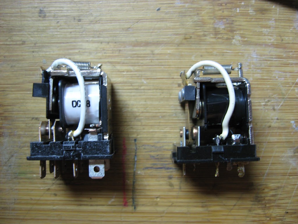
New vs old (The new one is on the left, the old one on the right):

SX-1980+SS+relays+new+vs+old.JPG


And the new relay in place! To get the old case to fit on the new relay all I had to do was file the front notch in the case a little taller. I also had to enlarge the holes in the board to small slots so the new relay terminals would fit, but after that it went in like a charm and worked perfectly! I have it playing right now. :thmbsp::banana:

SX-1980+new+SS+relay+in+place.JPG


And with this done that pretty much wraps this restore! Now if you will excuse me, I will now go have a serious listening session with it. :D
 
Last edited:
just a note, and not to detract from matts success, and a decent time has passed:

a 653-ly1-0-dc24 ($7.63 ca 6/2013) fits in just fine, all that is needed is to remove R102 2.2k 2w and run a wire over to the 24v at C203(3300uf 35v) + terminal.
Will run 2 watts or so cooler without the dropping dissipation of R102 to get (106 to 99 v unreg DC) down to 24v.

No slots to cut in the pc board either.... $12.40 (ca 6/2013) versus $7.63 doesn't hurt either
 
markthefixer said:
just a note, and not to detract from matts success, and a decent time has passed:

a 653-ly1-0-dc24 ($7.63 ca 6/2013) fits in just fine, all that is needed is to remove R102 2.2k 2w and run a wire over to the 24v at C203(3300uf 35v) + terminal.
Will run 2 watts or so cooler without the dropping dissipation of R102 to get (106 to 99 v unreg DC) down to 24v.

No slots to cut in the pc board either.... $12.40 (ca 6/2013) versus $7.63 doesn't hurt either

Not at all Mark, having an easier way of doing it is always better. :thmbsp: I had seen something mentioned about this mod when I started the restore originally, but at that point there was no confirmation that it was a good mod, at least that I remember. So, I went with what I did because I knew it would work without needing to mod the circuit, though the board modding I wasn't too hot on. Thank you for the info, I will probably try that for the next SX-1980 I do.

Edit: I just realized I forgot to update on something! I replaced the 35v zeners along with D208-D211, all 24v 1/2w zeners, so that is also done. It's been running several hundred hours since the restore and is now my go to receiver, I love this thing. Currently running a pair of Polk SDA-1C's, sound=perfection.
 
Last edited:
VERY lo tech question, but a sincere one none the less -
I am restoring my very first 1980 and I obviously do not want to "F" it up....this includes the bulbs. The previous owner had every intention to replace them, but it never advanced beyond the removal phase.
I am seriously tempted to go LED. I have done this with several other brands and the results have been remarkable. The soft glow of a Pioneer may be difficult to achieve, I fear.
Any suggestions? Stick with the traditional or go modern? And if do go modern, any tips on how to get the warm hue?
 
Matt is doing a complete restore for me right now on a SX-1980 and using LEDs for all the function indicators. He did a 1280 for me with LEDs that I thought was terrific.

That said, I would NOT use LEDs for the general illumination lamps. Just personally, at least, those need to stay actual incandescent bulbs. Not sure if Matt or anyone else ever has, but I'm just sayin'.

Yes Skylab - I think that is the way to go. Input appreciated.
 
Matt, it is far better to use the EchoWars current sources and get rid of the 24v zeners, 100 ohm and 22 ohm resistors and the 2sk34 jfet, it's presence is just an invitation for wandering spikes to take it out, the 24v zeners were in there to PROTECT the 2sk34... while with 180v & + transistors, the current sources are really really robust.

Frankly I'm surprised you were leaving them in.
 
Advice taken, I was under the impression that you only need to use EW current source mod if you need to replace a blown 2SK34. My bad. I'll research it and see if I can find the thread I saw the current source build mentioned in.
 
EchoWars SX-1980 2SK34 replacement current source instructions

Advice taken, I was under the impression that you only need to use EW current source mod if you need to replace a blown 2SK34. My bad. I'll research it and see if I can find the thread I saw the current source build mentioned in.

EchoWars Current Source Word Document Download Link

Here ya go... (see Word doc attachment)

The FET is a weak point. I tossed them, and replaced them with a home-made current source.

Read here: http://www.diyaudio.com/forums/showthread.php?s=&threadid=92904 I don't get into the current source till post #9.

The pic (mtf edit - schematic) below is the regulator with the mod installed. It eliminates R211, D209, D208, Q206, R214, and the same parts on the negative side.

attachment.php


mine in the picture uses the two zetex transistors and DEPENDS upon them being EBC layout.

parts (for one, make two for the SX-1980):
sx-1980 awr-154 Q206
sx-1980 awr-154 Q207
current source pos
npn npn transistor 522-ZTX696B $0.72
pnp pnp transistor 522-ZTX796A $1.39
1.2k 1.2k 1/4-1/8w 660-MFS1/4LCT52R122J $0.08
green led green led 604-WP132XGC $0.09
1 meg 1 meg 1/4-1/8w 660-MFS1/4DCT52R1004 $0.06


attachment.php


That is about as small as they can get without using surface mount components, and THEN you might have heat dissipation problems.

the holes are on 0.1 inch centers on a square grid, thus it has 6 holes long by three holes wide.

ANY board that connects three holes in a row will suffice, even from Radio Shack - in fact they are probably your cheapest alt6ernative with their small boards

522-ZTX796A PNP TO-92E ebc 200v 0.5a 1.5w 100mhz 100-800hfe $1.39 ea
522-ZTX696B NPN TO-92E ebc 180v 0.5a 1.5w 70mhz 150-500hfe $1.21 ea


ksp93 or ksp92 (pnp)
2n5551 (npn)

you NEED transistors with a EBC lead layout, to be able to use like in the pictures.

at least 150 volts, 50 to 100mA current, and 1/2 watt or more of power dissipation, speed isn't important, gain should be as high as readily available (but don't go nuts, look at the difference between the zetexes and the others I listed as guidelines), but you don't have to pursue perfection there...

as for the layout, the LED's are the only components that "skip over" a row of holes.

row, position from the pictures, six rows, with three hole positions on a 0.1 inch square matrix:
1.a 1.b 1.c
2.a 2.b 2.c
3.a 3.b 3.c
4.a 4.b 4.c
5.a 5.b 5.c
6.a 6.b 6.c

edit:
0 a b c
1 x x x
2 x x x
3 x x x
4 x x x
5 x x x
6 x x x


plus connection 1.b
1.2 k resistor 1.c to 2.b
led #1 anode 1.a
led #1 cathode 3.a
npn transistor collector 3.a
npn transistor base 4.a
npn transistor emitter 5.a
1 meg resistor 3.b to 4.b
pnp transistor emitter 2.c
pnp transistor base 3.c
pnn transistor collector 4.c
led #2 anode 4.c
led #2 cathode 6.c
1.2k resistor 5.b to 6.a
minus connection 6.b

do this right and 2.a, 5.c will be the only unused holes
and YES, there are two leads in one hole at locations 3.a and 4.c
3.a is one led's cathode and the npn transistor's collector
4.c is the other led's anode and the pnp transistor's collector

don't laugh at the directions, it took quite a while to come up with an accurate verbal description that would loose nothing upon any translations.

attachment.php

and, here's Lee's (Overundr1) first build too (it has a slightly different pattern in back, not connected across all three holes in one row:

attachment.php
 
Last edited:
Okay, I have them built (finally!) and have been trying to figure out the best way for them to fit. They are built exactly like yours, Mark. Based on EW's Word doc, I think I have it down, but I just wanted to make sure of the fact. The image below shows what I had in mind for putting them in, will that work? Note: the photo is of the +80v regulator, I know I need to reverse it for the -80v regulator.
 

Attachments

  • SX-1980 SK34 mod placement.jpg
    SX-1980 SK34 mod placement.jpg
    109.1 KB · Views: 326
Last edited:
Installing the EchoWars current source on a SX-1980

Here it is, publicly, my most formerly guarded information... :D

So, those out there who made a promise, you are released from your promise...

Since I had ALL the rest of the regulator info out there, (and people were using it)
I thought I'd better get the installation instructions out there too...
to prevent having to make more of them, if anybody else blew something up
because I was stingy with the installation instructions.


Positive regulator
pos_reg_AK_post.jpg

Negative regulator
neg_reg_AK_post.jpg
edit: WARNING, in this picture the zener diode string for D213 is INCORRECTLY installed into the D215 position. Meanwhile the D215 diode is in the D213 position.
 
Last edited:
markthefixer said:
Here it is, publicly, my most formerly guarded information...

So, those out there who made a promise, you are released from your promise...

Since I had ALL the rest of the regulator info out there, (and people were using it)
I thought I'd better get the installation instructions out there too...
to prevent having to make more of them, if anybody else blew something up
because I was stingy with the installation instructions.

Thank you very, very much Mark, those photos helped a lot. I'm doing mine and Skylab's with these, most of his -80v regulator got butchered and was replaced with NTE parts, lifted traces etc. Not pretty in short, but it looks a lot better then when I started. I've been trying to locate a persistent hum that's present in both channels and traced it to the -80v regulator using the oscilloscope, but even after taking out the NTE parts and putting these in, it was still humming! Ugh.

Turns out R212, the 5.6 ohm 1/2w resistor was replaced with an old (like mid 1960's old) carbon composition resistor and it reads 0.5 ohms. Ouch. I looked right at it and didn't even think it looked out of place until I looked at mine which still has the stock resistor. :sigh: You old guys aren't the only ones who get brain farts. :D I checked all the other parts in the regulator (which I know I should have done after seeing almost the entire regulator had been poorly rebuilt) and they are either already replaced by me or are original and measure fine.
 
Mark ,

a 653-ly1-0-dc24 ($7.63 ca 6/2013) fits in just fine, all that is needed is to remove R102 2.2k 2w and run a wire over to the 24v at C203(3300uf 35v) + terminal.
Will run 2 watts or so cooler without the dropping dissipation of R102 to get (106 to 99 v unreg DC) down to 24v.


Isn't R102 = 3.3K (2W) ?:scratch2:
 
As far as the obsolete parts, I'm thinking SMD. I see some on mouser rated at 2 and 2.75 watts. Unless anyone has a known *good* sub?
 
ZTX796/ksp93 obsolete, any words of wisdom on subs?

yep:

npn transistor 522-ZTX696B
pnp transistor 522-ZTX796A
npn transistor 512-2N5551BU or ksp42??
pnp transistor 512-KSP92TA
1.2k 1/4-1/8w 660-MFS1/4LCT52R122J
green led 604-WP132XGC
1 meg 1/4-1/8w 660-MFS1/4DCT52R1004

using the 512-2N5551BU and 512-KSP92TA

522-ZTX795A PNP TO-92E ebc 140v 0.5a 1.5w 100mhz 100-800hfe $1.44 ea
obs-ZTX796A PNP TO-92E ebc 200v 0.5a 1.5w 100mhz 100-800hfe $1.39 ea

522-ZTX694B NPN TO-92E ebc 120v 0.5a 1.5w 130mhz 150-500hfe $1.21 ea
522-ZTX696B NPN TO-92E ebc 180v 0.5a 1.5w 70mhz 150-500hfe $1.21 ea

512-ksp42bu pnp to-92 ebc 300 0.5a 0.625w 50mhz 40-100hfe
512-ksp43bu pnp to-92 ebc 200 0.5a 0.625w 50mhz 40-100hfe

512-ksp92bu npn to-92 ebc 300 0.5a 0.625w 50mhz 40-100hfe
512-ksp93bu npn to-92 ebc 200 0.5a 0.625w 50mhz 40-100hfe

512-2n5551 pnp to-92 ebc 160v 0.6a 0.625w 100mhz 30-250hfe

zetex gets 2.2mA
Fairchild is 2.09 to 2.1mA

2n5551 and ksp92 have been used extensively with no problems.

I need the ebc layout for my simplified perf-board layout.
 
Back
Top Bottom