• The move to the new server is done. There are some software and database maintenance updates in process. This has us passing the hat around to help out. We appreciate any donations. Seriously, even a dollar helps. The payment page may be found here - https://www.audiokarma.org/support.html

KT88 SE Abdellah (modified by Alex Gendrano) + AK..

That's good news to hear. :thmbsp:

And yes checking all the voltages is a good thing to.
(when you do calculate the output tube dissipation)

Some voltages are weird.. :drool:
B+ vdc: 395-396
Driver vdc:
pin 1: 96-98
pin 3: 3.36
pin 6: 116
pin 8: 3.28-3.29
May be I have to change a cathode resistor to make both channels equal?

About the 6CA7EHs..
pin 8: 20
pin 8: 26-28

Tried measuring the plates in both tubes but my meter says "1" as not being able to measure it??.... :scratch2:
 
Last edited:
First I would swap the output tubes from side to side and see if
that voltage at pin 8 follows the tube, if it does you have a very
weak tube and it needs to be replaced, (the one with 20 that is).

Second the variance in the driver tube plate voltage is more then
likely just not a very well matched tube section to section, try an
couple other tubes and check there voltages to verify it is not the
circuit but just the tube not very well matched.
 
First I would swap the output tubes from side to side and see if
that voltage at pin 8 follows the tube, if it does you have a very
weak tube and it needs to be replaced, (the one with 20 that is).

Second the variance in the driver tube plate voltage is more then
likely just not a very well matched tube section to section, try an
couple other tubes and check there voltages to verify it is not the
circuit but just the tube not very well matched.

Yes, swapping output tubes will be the next.
About the driver variance.. Should I swap cathode wires and see if voltage in pins 3 and 8 remain the same ??
I suspect difference in both leds..
 
Measured again. This time with volume pot in 10, but with no sound in input.
Last time was measured with music playing..
Swapped tubes. This was the result:

6CA7 tube LEFT (before was right) - pin 3: 370-371 vdc
6CA7 tube LEFT - pin 8: 29 vdc
6CA7 tube RIGHT pin 3: 370-371 vdc
6CA7 tube RIGHT pin 8: 29 vdc

Driver - pin 1: 107-108 vdc
Driver - pin 3: 3.27-3.28 vdc
Driver - pin 6: 117 vdc
Driver - pin 8: 3.22 vdc

B+: 383 vdc

Again, one thing I noticed is that when volume pot is in 6-8 range, is not as clear as 1-6 and 8-10 range. I measured B+ and between 6-8 it goes up to 410vdc.
Any explanation to that??
 
Last edited:
The output tube voltages look pretty normal there,
Just keep an eye on the one that measured 20 before.

The driver tube again is probably just an imbalance and
difference between the 2 sections, not very well matched.
(nothing wrong but another tube may be better matched)

---------------

The B+ to volume pot I have no idea nor the sound degradation
except some form of oscillation, which you'll have to track down.

If you have some way to control volume without that darn volume
pot I would just remove it and replace the 1meg resistor with a 100
to 270k resistor and be done with it if that works fine with no issues.
 
The output tube voltages look pretty normal there,
Just keep an eye on the one that measured 20 before.

The driver tube again is probably just an imbalance and
difference between the 2 sections, not very well matched.
(nothing wrong but another tube may be better matched)

---------------

The B+ to volume pot I have no idea nor the sound degradation
except some form of oscillation, which you'll have to track down.

If you have some way to control volume without that darn volume
pot I would just remove it and replace the 1meg resistor with a 100
to 270k resistor and be done with it if that works fine with no issues.

Ill try to get a new driver then, and will keep an eye on that output tube.
What is my plate dissipation with those values?

About the volume Im afraid I dont have a preamp yet. :tears:
Ill must track that problem down. Any reason why B+ could increase in that range of the pot?
About that oscillation, if it exist, how may I find it?

Thanks!!
 
Plate dissipation is about 19w.

Sorry but yur last 2 questions I don't have an answer for.
I would have to have the amp and work on it to find them.
What yur describing makes no sense to me an hasn't come
up on any builds I've done on this or anyone else has either.

All I can say is keep checking everything, maybe step back a
bit, and look over all your wiring and the build is correct there.
 
Plate dissipation is about 19w.

Sorry but yur last 2 questions I don't have an answer for.
I would have to have the amp and work on it to find them.
What yur describing makes no sense to me an hasn't come
up on any builds I've done on this or anyone else has either.

All I can say is keep checking everything, maybe step back a
bit, and look over all your wiring and the build is correct there.

Ill replace two wires with RG174 and see how it goes.
They are the closer to the B+ so Ill start from there.

I have still a couple of questions:
1. How do you calculate that 19W??
2. What are the suggested value of Vrms for the input?
3. Do you recommed triode or UL for this amp? Pros and Cos ?

And finally, what preamp do you have?
Thanks Kegger!
 
To quickly answer a couple questions..

370v at the plate minus say 30v from the cathode = 340v plate to cathode.
30v at there cathode divided by that 500ohm resistor = .060 or 60 milliamps.
Minus say 4.5ma for the screen and you have .0555 x 340 = 18.87 watt diss.

It's about 2.8v input to drive the amp to full power with 6DJ8, 1.8 with 6AQ8.

And my main preamp is an Anthem 6DJ8 based Pre-2L, Triode/UL is your call. ;)
 
Last edited:
To quickly answer a couple questions..

370v at the plate minus say 30v from the cathode = 340v plate to cathode.
30v at there cathode divided by that 500ohm resistor = .060 or 60 milliamps.
Minus say 4.5ma for the screen and you have .0555 x 340 = 18.87 watt diss.

It's about 2.8v input to drive the amp to full power with 6DJ8, 1.8 with 6AQ8.

And my main preamp is an Anthem 6DJ8 based Pre-2L, Triode/UL is your call. ;)

Thanks Kegger!
Can I change ECC88 for a 6AQ8 without changing cathode resistor?
I have ECC88 with red led and 200R cathode resistor now.

About that 4.5ma, how can I measure it exactly?
 
Yes the 6AQ8 should just drop in there.

To measure the screen current measure the voltage drop on the screen gird resistor.
(not that it matters as it's not critical)
 
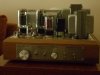
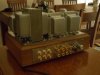
Hello. I attach 2 pictures of the amp finished, and another one of the inside.:music:
One of my regrets.. wish the box was bigger.
 

Attachments

  • P1010448.jpg
    P1010448.jpg
    52.4 KB · Views: 252
  • P1010449.jpg
    P1010449.jpg
    59.9 KB · Views: 224
  • P1010438.jpg
    P1010438.jpg
    80.9 KB · Views: 239
I meant to comment on this.. :)

It looks very very nice, I like it a lot..:thmbsp:
But how close is that power tranny to the output tranny?
 
I meant to comment on this.. :)

It looks very very nice, I like it a lot..:thmbsp:
But how close is that power tranny to the output tranny?

Its extremely close. Wish I have a widther chassis. However pt is turned 90 degrees of the ot's..
 
By the way.. My JJ ECC88 started to fail in less than 10 hours of use. :nono:
Replaced it with a NOS Hungarian Tungsram ECC85. Lets see if I am luckier this time.
 
The 6BS8 is very similar to the 6BK7/6BZ7/6BQ7 I've mentioned a few times.
There fine tubes an should work in the circuit here without any issues there.
 
The 6BS8 is very similar to the 6BK7/6BZ7/6BQ7 I've mentioned a few times.
There fine tubes an should work in the circuit here without any issues there.

May be a stupid question, but.. any reason why you prefer the ECC85 over the ECC88 in this circuit?
 
Overall it's just a better tube in THIS circuit.

The gain is just about right, and the larger plate resistance works the feedback well.
(and to me sounds a bit better as well)
 
This would be the makeup of how I would setup the amp your looking at. ;)
Any resistor wattage not listed would be 1/2w, all cap voltages are minimum.

The KT88(and others) have G3 connected to the cathode internally, so there
is only 2 grid connections, input/g1 and screen/g2, the EL34 has the separate
G3 and cathode connections so that you connect pin1 and pin8 together just
like it is done on other amps. (so connect pin1 an pin8, so all the tubes work)
.

Kegger I would like to build the parallel version of your amp. For a stereo amp with 2 6dj8 and 4 KT88 is 250mA Power supply enough? Thanks Brian
 

Attachments

  • KT88-SE_UL_fbk_LED_6DJ8_prl (1).GIF
    KT88-SE_UL_fbk_LED_6DJ8_prl (1).GIF
    7.4 KB · Views: 488
Last edited:
Back
Top Bottom