• The move to the new server is done. There are some software and database maintenance updates in process. This has us passing the hat around to help out. We appreciate any donations. Seriously, even a dollar helps. The payment page may be found here - https://www.audiokarma.org/support.html

Can I increase capacitance on these TONE BOARD caps?

roger2

.
Subscriber
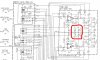
My question is in regards to caps Ci15 and Ci16 shown in the schematic attached. They are currently 100uF/10v. It would be just as easy to replace these with 220uF/10v as they are close to the same physical size as the original caps. I will be using Panasonic FM and voltage rating would remain the same.

It would appear to me (I don't know, that is why I ask) that these two caps serve the same function for the opamp on this board that the main power supply caps serve for the main outputs. Main PS caps are routinely increased in size. Could increasing capacitance of these two caps on the tone board deliver better power to the opamp during transients?

Could it be detrimental to this circuit to increase capacitance of these two caps? If so why? Could it be beneficial?
 

Attachments

  • !tone amp w defeat switch enlarged 235 in pdf.JPG
    !tone amp w defeat switch enlarged 235 in pdf.JPG
    80.3 KB · Views: 145
Last edited:
Register to hide this ad
I doubt if there's anything to gain by increasing their value, but it certainly would not hurt anything. These caps are just a local filter for the opamp.
 
Hi,

sreten *AK Member* Join Date: Dec 2010Location: Brighton U.K.Posts: 172
They are AC coupling caps and do very different things than power supply caps.
Pretty pointless upping the values. Bypassing them with film caps is an idea.

rgds, sreten.
 
Just to add a tweak. The caps are the local audio ground for audio passing through that op-amp, so in theory increasing the value lowers the high -pass cutoff frequence, but the difference is academic. For greater reliability, why not use 100uF at 25 volt? I think that would be a better upgrade.
 
My question is in regards to caps Ci15 and Ci16 shown in the schematic attached. They are currently 100uF/10v. It would be just as easy to replace these with 220uF/10v as they are close to the same physical size as the original caps. I will be using Panasonic FM and voltage rating would remain the same.

I would appear to me (I don't know, that is why I ask) that these two caps serve the same function for the opamp on this board that the main power supply caps serve for the main outputs. Main PS caps are routinely increased in size. Could increasing capacity of these two caps on the tone board deliver better power to the opamp during transients?

Could it be detrimental to this circuit to increase capacitance of these two caps? If so why? Could it be beneficial?


Not so fast!

I would be cautious about increasing those caps. In fact, they are not bypass, coupling or filter caps, per se. Ci15 and Ci16 work in tandem with Ri27 and Ri28 to adjust the turn-on and turn-off timing of ICi1. Adjusting them won't do anything for the audio, but might result in pops or thumps.

-k
 
The 100uF caps (Ci15 and Ci16) are part of the power supply only. I agree that a 10V cap on a 9V supply line is borderline. Use a 16V (or more) cap here.

For the ripple reduction between a 100uF and a 220uF, on op-amps... I don't think you will perceive any amelioration.
 
Hi,

They are not part of the power supply or anything to do with turn on / off.

They are there to keep DC out of the tone pots, voltage rating is fine.

There is little point changing them, possibly bypass with film types.

rgds, sreten.
 
My question is in regards to caps Ci15 and Ci16 shown in the schematic attached. They are currently 100uF/10v.

Ci15 is connected to pin 8 of the dual IC (4558). This is the positive supply line for the IC.

Ci16 is connected to pin 4 of the IC. This is the negative supply line.
 
There is a reason for the conflicting advice. The caps are labeled Ci15 not C15 and Ci16 instead of C16. Some of us are mistaking the caps on the outputs of the op amps Ci5 and Ci6 for the normal convention of C15 and C16 (no i in the part number). Ci5 and Ci6 are output coupling caps and should remain the same value. Ci15 and Ci16 can be found on the schematic at the ground buss between the outputs of the op amps. One end of each is grounded and the other end is attached to the 9 volt (+ or -) of the power feeds to the op amps. They are part of the power supply and may be increased safely.

attachment.php


Shelly_D

Edit: It would be a good idea to increase the voltage rating of those as a previous poster noted. 10 volt caps on a 9 volt supply is pretty thin operating margin.
 

Attachments

  • !tone amp w defeat switch enlarged 235 in pdf.JPG
    !tone amp w defeat switch enlarged 235 in pdf.JPG
    82.3 KB · Views: 378
General Tip

Here is a tip for the OP and others that may want to ask similar questions on a schematic. Highlighting the part of the schematic like I have is a great way to draw the attention of those you are asking for help to the parts in question. Don't need a whole lot of graphics editing software. I used Windows Paint to edit this one. Since Win XP it handles a whole lot more then just BMP files.

Shelly_D
 
Good catch shelly_d, and excellent advice regarding use of markings for clarification.

Also want to say thanks to everyone who posted here. Quite a knowledgeable and capable group ("State of the Art" one might say :D )

...(edit)...For the ripple reduction between a 100uF and a 220uF, on op-amps... I don't think you will perceive any amelioration.

No doubt this is correct. You are wise and experienced. I am suffering a newb-related affliction resulting in compulsive desire to implement any subtle or slight "mod" that I can, even to a lower-end amp like this one (but ONLY if I know any such mod will have no negative effects). By the time I get to my 3rd or 4th project my priorities will (hopefully) become more inline with the realities of costs vs benefits...

But for now I am a slave to my own, non-knowledge based, imaginings: that some slight modification or attention to some minute detail might possibly make a difference.

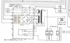
For example, when I re-do the power supply (pic attached) my plan is to use 1% metal film for resistors Rk1 and Rk2, and 2% zeners to replace ZDk1 and ZDk2 (yellow marked). My thinking is that it would be good to get all voltages matched as closely as possible between the B+ and B- legs that feed power to the preamp and tone boards.

Is there any merit to this idea? Or is this something that won't hurt but probably won't help much?


I have couple further questions:

1) is there any way to match the 14v shunt zeners? I will have 10 of them (for $.26) so I could use the closest matched pair

2) regarding caps Ck3 and Ck4, (marked in red) is it safe to increase the capacity of these? They are originally 470uF. I can go to 680uF or 1000uF using same voltage as original with plenty of space physically. Does ESR, in the upper frequencies, increase or decrease with higher capacitance?

Attachment: power supply from same amp as the OP (Kenwood KA-4006)
 

Attachments

  • !power supply enlarged 266 in pdf - marked.JPG
    !power supply enlarged 266 in pdf - marked.JPG
    49.7 KB · Views: 41
Last edited:
ESR is generally measured at 100KHz, to eliminate the effects of capacitance in the measurement and isolate the series resistance component. At audio frequencies, more capacitance and lower ESR might both be beneficial, if the original design was deficient. If you're powering discrete circuitry, rather than op-amps, then going up from 470uF could make a difference. Film or ceramic bypasses also might help. Good op-amps have such high power supply rejection ratio (PSRR) that cleaner supply rails usually have little to zero effect on performance.

It's unlikely that matched zeners will have any effect on performance. If you want to do it anyway, I suggest rigging clip leads directly to the application circuit, to insure that you achieve good matching at the actual bias currents in use. Don't disconnect either zener while the amp is powered up.
 
All your planed changes in this case are safe to implement. Without knowing the downstream circuit these are feeding it's impossible to know if the changes will give you any benefit.

One comment for you to check. The schematic shows -14 volts coming off the plus terminal of capacitor CK3. Since the other end of the cap is shown connected to ground, this does not compute. Before messing with these parts, best to measure the voltage across the 2 caps and the voltage between each of the cap terminals and ground to determine for sure the polarity needed. Most likely the error is the voltage marking, but you should make sure of that with a meter before changing the parts.

Also, once again, you have a very narrow margin between the operating spec of the cap (16V) and the operational voltage of the amp (14V). Increasing the voltage rating of the caps would be a good thing to do here.

Shelly_D
 
.... At audio frequencies, more capacitance and lower ESR might both be beneficial, if the original design was deficient. ....

My thinking is that if the original 470uF caps' function is primarily to serve as a power reserve or ripple filter, then more uF couldn't hurt. Similar to the increase that is routinely made in main PS caps. But I don't know if my logic is sound or if there could be any possible negative effects (that is why I asked about ESR)

....If you're powering discrete circuitry, rather than op-amps, then going up from 470uF could make a difference. Film or ceramic bypasses also might help.....

The +/- 14v rails feed only the tone amp discussed at the start of this thread and the phono preamp which uses the same opamp but with +/- 13v rails as opposed to the +/- 9v rails used in the tone amp ( hope I am using the term "rails" correctly :scratch2:)

....Good op-amps have such high power supply rejection ratio (PSRR) that cleaner supply rails usually have little to zero effect on performance.....

I have no reason to believe that these are good opamps. In fact, I have found some negative comments on older threads regarding these opamps. I intend to start a separate thread on this topic later. But, as relates to your comment, are these "good" opamps or no?

All your planed changes in this case are safe to implement. Without knowing the downstream circuit these are feeding it's impossible to know if the changes will give you any benefit....

answered above: just the tone board and a phono-pre, not pictured but using the same opamp receiving 13v instead of 9v

...One comment for you to check. The schematic shows -14 volts coming off the plus terminal of capacitor CK3. Since the other end of the cap is shown connected to ground, this does not compute....

I believe that the -14 marking you refer to is actually +14 on the schematic and is intended to apply to Pin 8 of the power supply board. The process of cutting'n'pasting, enlarging, etc has made some of the markings blurry. Pins 8, 9 and 10 supply DC to the tone and phono boards.

...Before messing with these parts, best to measure the voltage across the 2 caps and the voltage between each of the cap terminals and ground to determine for sure the polarity needed. Most likely the error is the voltage marking, but you should make sure of that with a meter before changing the parts...

I just verified the polarities with my DMM. I also intend to measure and record voltages everywhere on the PS board before making any changes.

As of now I have measured just one place and did find a discrepancy: I find 14.24v between pin 8 and pin 9 (gnd) but there is 14.44v between pin 10 and pin 9.

It is this discrepancy that I hope to eliminate by using the best matched parts I can. Is .2v enough to be concerned about for this circuit?

.
 
Last edited:
The older 4558's were not that great an op-amp, noisy...but used EVERYWHERE from guitar amps to stompbox pedals to mixing consoles. If that op-amp is socketed a NE5532 would be an easy swap--pull the old one out, put the new one in--and possibly you may notice it being quieter. Then save that old opamp and sell it to some guitar pedal nut who insists on having ancient 4558's.

.Oh, though they are noisy the 4558's still have good PSRR...
 
My question is in regards to caps Ci15 and Ci16 shown in the schematic attached. They are currently 100uF/10v. It would be just as easy to replace these with 220uF/10v as they are close to the same physical size as the original caps. I will be using Panasonic FM and voltage rating would remain the same.

It would appear to me (I don't know, that is why I ask) that these two caps serve the same function for the opamp on this board that the main power supply caps serve for the main outputs. Main PS caps are routinely increased in size. Could increasing capacitance of these two caps on the tone board deliver better power to the opamp during transients?

Could it be detrimental to this circuit to increase capacitance of these two caps? If so why? Could it be beneficial?

It would be better to focus on the Op amp itself rather than the passive components.
 
Is a complete schematic available? I suspect it would make sense to upgrade these op-amps and upgrade their power supply to +/-18V at the same time.
 
Link to schematics provided to me by ecluser in this post

Note that there are two pages, the second page is a revised main amp board with protection relay. My amp does use the revised main amp board, although this probably has nothing to do with the questions I am asking in this thread.

The pics I posted in this thread are from the schematic page which shows the entire amp but with the old main amp board.
 
Last edited:
re: the 4558 opamps

Could someone please follow up on comments made regarding the 4558's (starting with nashvillebill's post on this page)

What does it mean to say that they are noisy and how bad are they compared to modern opamps? What would the noise sound like? Do opamps drift with age like small transistors do? Or were these an inferior design?

I believe that this one has put out a bit of heat over the course of its lifetime because I noticed that the two original caps (NOT shown in this pic) nearest to it had dark discoloration on the side that faced the opamp.

Pic attached below is the tone board showing one of the 4558's from @ 1974.


picture.php
 
Last edited:
Back
Top Bottom