ecluser
Super Member
um...I have had a very long day. I don't understand what perforated board is in this context. Is this generic PCB material?
http://www.elexp.com/pro_pb18.htm


um...I have had a very long day. I don't understand what perforated board is in this context. Is this generic PCB material?

.... it is probably a good idea to stick with the stock values for Ci15 & 16...(edited)...without a scope you're flying blind. I can think of a LOT of fairly fast (10 to 20V/µS) that run peachy with even very poor bypassing, but there's never a guarantee. The safe suggestion is to keep the stock opamp in place, as you (roger2) simply don't have the tools needed to be tackling anything very deep here. And most opamp swaps will require that Ri27 & 28 be changed IF you wanted to keep the stock supply voltage to the chip.....


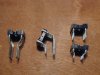
First pic shows my socket candidates, beginning with the wirewrap type suggested by Ken Kantor. The legs on this were clearly long enough. The only problem was that the legs were too fat to fit through the holes in the PCB. This PCB has very flimsy traces and small pads that will flake off for any or no good reason. I did not want to risk drilling into it.
Next up is a right angle socket which I slightly modified by spreading the legs from their original .1 spacing. Again, this could have worked here. But close proximity to resistors Ri7,8 would have prevented removal of the opamp after installation and would have required soldering the socket with opamp in place.
The winner was what Mill-Max calls a "Long Solder Tail" socket. The tails are .170" long - enough to work where the shorter tails on a generic Radio Shack socket (earlier in this thread) did not.
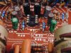
Second pic shows the tone board in its current state. I did (finally) get 16v caps into positions Ci15,16 (power supply decoupling?).
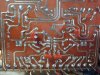
Third pic shows .22uF ECQ-V bypass caps on Ci15,16 as well as Ci5,6 (the bi-polars on the outputs of the opamp).
<schematic of this board appears in posts 1 and 10 on page 1 of this thread>
.....Some of them behave better with ceramics or other types of decoupling caps from both supply pins to a high-quality ground system instead......
@ Ken Kantor
Seems to be working OK with either NJM4558 or 4559. But the sound seems sterile or maybe even a bit harsh at higher volume.
However, in addition to using the new opamps I also changed out several of the old carbon film (I assume) resistors to metal film. Some key ones most likely and this is the preamp. So I do not know whether to attribute (my perceived) change in sound to the different opamps or the different resistors.
I am getting together a Digi-Key order for the OPA2134, an additional decoupling cap (referred to in last post) and new carbon film resistors.
The TL072's low input bias current offers the possibility of modifying the circuits to eliminate electrolytic input coupling caps in favor of films, but that's already a strong possibility in the tone amp....
...Of these choices, I would definitely go for the 5532 because of its low noise and superior load driving capability. The phono preamp chip has to drive 560R at high frequencies due to RIAA equalization, which is just barely acceptable even for op-amps with plenty of grunt like this one. And I would boost both supply rails to 15~18V in order to maximize phono preamp headroom.
Wouldn't the OPA2134 offer the same possibility as the TL072, both having FET inputs and low input bias current? (even lower on the 2134 than theTL072)
Would I have been incorrect to assume that films could be used here regardless of the opamp in use? In what situation (physical size notwithstanding) would electrolytic be preferable film?
But changing rail voltages of two boards to accommodate the 5532's higher operating current seems like an avoidable complication. I don't want to mess with the gain structure of the amp. And honestly, I am not concerned about the phono section. If I raise the Vf of the zeners on the PS board that would require adjustment of the phono board resistors. I did put a socket and a new NJM4558 in the phono section and am happy to leave it alone now.
If possible, what I would like to do is find an opamp, to replace the 4558 on the tone board, that would require a minimum of component changes and that could operate at the original +/-9v. Just to keep things simple for a rookie. Maybe that is not possible I don't know, but right now it seems like a reasonable initial goal.
.... And honestly, I am not concerned about the phono section. If I raise the Vf of the zeners on the PS board that would require adjustment of the phono board resistors. I did put a socket and a new NJM4558 in the phono section and am happy to leave it alone now....