
• The move to the new server is done. There are some software and database maintenance updates in process. This has us passing the hat around to help out. We appreciate any donations. Seriously, even a dollar helps. The payment page may be found here - https://www.audiokarma.org/support.html

SX-525 Refurb

Rockmore

Active Member
Banned
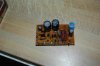
This is the PS board out of my xs-525. Sorry for the blurry shots- dont have a zoom or macro lens.

- There is a glop of clear silicone or like household goop between the two 35v 330-uf and 50v 220uf larger black caps at the base of them and on the board.. Never seen this before. Could this of actually been for adhesion for some reason from the factory in 1972? Receiver has never been anywhere for repair ever, and cover has never even been off... Solder joints all good, so cant figure it out.
And when I replace the caps, do I need this adhesion or whatever?

- The crap colored resistor looking like component to the right; states 2B a circle with a apparent S inside it J 390 omega upside down F and the resistor director directly to the right of it, looks all burnt or black discoloration on the board directly beneath them. Instead of just recapping this board, should I replace every single component then from this apparent damage?

- Where can I get a service manual for my sx-525? Already received a schematic.

Thanks guys
 

Attachments

  • DSC_0693.jpg
    DSC_0693.jpg
    127 KB · Views: 175
  • DSC_0700.jpg
    DSC_0700.jpg
    45.1 KB · Views: 194
Register to hide this ad
This is the PS board out of my xs-525. Sorry for the blurry shots- dont have a zoom or macro lens.

- There is a glop of clear silicone or like household goop between the two 35v 330-uf and 50v 220uf larger black caps at the base of them and on the board.. Never seen this before. Could this of actually been for adhesion for some reason from the factory in 1972? Receiver has never been anywhere for repair ever, and cover has never even been off... Solder joints all good, so cant figure it out.
And when I replace the caps, do I need this adhesion or whatever?

- The crap colored resistor looking like component to the right; states 2B a circle with a apparent S inside it J 390 omega upside down F and the resistor director directly to the right of it, looks all burnt or black discoloration on the board directly beneath them. Instead of just recapping this board, should I replace every single component then from this apparent damage?

- Where can I get a service manual for my sx-525? Already received a schematic.

Thanks guys
I THOUGHT I PM'd you a link to a manual resource - if you want to buy a paper manual -Rick at stereomanual.com has the best reproductions in the business.
oops, I just checked, the best available at kallhovde.com or the tri-comp section is the 5 page schematic of the individual boards.


The glue was only needed for production at the factory - remove it with sharp instruments when replacing the caps.

Some boards will look like that even when they are still ok.

If the component reads in value - then leave it be.

There is just one transistor on the power supply, and two zener diodes. Very simple.

Since some where I read that your 525 was working, Just do the electrolytic (wet) caps.

If you've seen the lists we've done on other threads, use the schematics as a starting point, then visually verify each and every cap, make the list and post it, and I'll come up with parts numbers.

OH, I just saw the pictures - please DON'T cut or unwind any more wires!!! They never go back right, and they LOVE to break off short!!
 
Last edited:
Thanks Mark... looks like insomnia isnt uncommon LOL.

Dont need a paper manual, and I have the schematic. Just thought there might be other info in a service manual that would be handy.

Found kallhovde.com from your PM. Thanks!

Was going to ask you about the diodes and the transistor- beat me to the punch. One diode doesnt look good at all but will test everything. Thought I WOULD have to replace the transistor from the apparent damage on that burnt board area.

Just for kicks while youre here- any recommendations in these days and times for better electrolytic caps- ie: NOT replacing with electrolytic but other? Or sticking with electrolytic and a really good brand name etc?

(This is great therapy and distraction from the court cases I'm prosecuting at the moment.. ).

Thanks again
 
We'll get to that.... after the list and I start cross referencing the schematic - but to do that justice, the parts list that's part of the manual would be highly useful.
If Rick has it, it'll be about or under $25, and I doubt that at worst we spend $20 on parts for a huge number of replacements.

And we'll avoid the tuner - to avoid the need for a tuner alignment.

As a thumbnail guide, any cap in the range of 0.1 to 1.0 uf that's an electrolytic will be replaced with stacked poly film caps - which are bi-polar (uni-polar? non-polar?) - as in NO polarity differentiation.
 
Sent by PM by Rockmore to MTF said:
Ok... I'm attaching what I've got if you even need it to the post. PM still wont let me attach anything.

- Ive been referencing this thread as kind of a quality of parts spot: http://audiokarma.org/forums/showthread.php?t=269886 Cost isnt exactly an issue. I would like to replace anything with just about the best or good as exist now since its such a hassle finally getting in my receiver.

That is a view shared by MANY excellent Technicians, and in my opinion worth quite a few "brownie points", as going back in over and over just exposes the equipment to more risk and wear 'n tear

- I also thought I would like to replace the huge 63v 3300uf black neg polarized cap, and the two larger 35v 2200uf caps. Good idea?

If they're leaking, otherwise modern replacements are harder to mount in the same place because they are smaller, and a lot more selection effort is needed to get the electrical connections done well and neatly. Their failure is mainly to drying out, and the big ones have lots more water to loose before problems ensue, that's why the little caps are the most vulnerable.

- Are we going to use that other rule-of-thumb to replace ANY of the caps I replace, regardless of type and rating, with a little larger voltage ones? I thought I kept reading to do that...

within reason, but the power supply is the predominant place to increase voltages - old specs said 10% but allowed 15% over voltage w/o damage - but nowadays that 10% margin is razor thin

- Would like to obtain all the caps and parts etc from one source if possible. I need other things as well like a decent inexpensive solder sucker etc.. Im tired of using wick.

mouser.com or digikey.com, might take a bit of digging to narrow down the choices, but once you learn to use their site's searches, you'll do fine

- I dont really care about the tuner section, like you stated. As long as its not causing problems for the rest of the amp (receiver). I use a really nice fully modified Sony XDR-F1HD tuner anyways for everything. (eve though I went to all the trouble of finding and replacing the micro lamp for the tuner dial. Mine's orange).

- Ive also got a couple large ceramic type caps heavily shielded on the PS itself, as well as a coupe large fuse looking tubes soldered and shielded to the PS. Replace them?

Just electrolytic caps (mostly over 1 microfarad), the rest don't have much of a failure rate, the soldered in fuses - well think about it solder = heat, fuses need heat to "blow" (or assemble them) thus heat = not good (in my opinion)


- I want to replace the completely annoying and hassle bound speaker terminal "clips" (dont have the part numbers in front of me) with some sort of functional wire attaching binding posts. Ideas? Saw where another guy merely came up with a rca females block soldered to those slide in clips for the mod, but I dont want to do that. i want to keep the slide in's for parts.

That's a whole project in itself. There are threads with alternate solutions and measurements as well, which I will add to eventually (work in progress) but will undoubtably turn out to be way too expensive and labor intensive

- I had also thought about hand making a new power cord and, but the way its all soldered and attached to the PS its looks like a real hassle and job. Mine stock is really thin and isnt even polarized or grounded (the cord wire and the plug.

it's non-polarized on purpose, reversing the plug in the power socket is a cure for hum reduction, plus the receiver wasn't constructed in such a way that a 3 wire cord could be easily used.

THESE are ALL forum appropriate questions, and I don't mind answering them online
BUT
I have asked you to keep it in the forums and not PM me with them. There is NO private advice, it's all public
- AND -
there are NO dumb questions, just questions that the answers haven't been posted already, or answers that are hard to find.

PLUS, other people have been at where you are now at, and THEIR advice is as valuable or even MORE valuable than mine. But HOW can they share if they never SEE the question?

Rockmore said:
need your email IF you want or need the schematics and what I've got. Found the owners manual also, just not a "service manual" so far.

Audiokarma has a forum called "Digital Docs", and lots of people can benefit (and are willing to help get them in there ) from the documents being posted in there.

I don't want to discourage you, it's just that PM's are inconvenient (pita really) to service, cuz when the buffer fills up, people with equipment HERE (AT casa mtf) can't get hold of me.... so I HAVE to keep it available.
 
Last edited:
I don't want to discourage you, it's just that PM's are inconvenient (pita really) to service, cuz when the buffer fills up, people with equipment HERE (AT casa mtf) can't get hold of me.... so I HAVE to keep it available.

The subscribe and have a PM box capacity of 1250... :smoke:
 
Edit: I mentioned scanning a manual, unfortunately, it appears I don't actual have a full one, I could scan what I have, but I lack the parts list, I have the operating instructions, advert, and schematics. If any of those could help, or your interested, I can scan them...

Other than that, I hope you get it sorted out, that's a great little receiver, I love mine:thmbsp:.
 
Last edited:
The subscribe and have a PM box capacity of 1250... :smoke:

Don't think it doesn't tempt me, but I always seem to be a bit shy of the price of subscription. And every time I think I may be catching up, it turns out that something ELSE has been in the works to upset the apple cart. These last 3 months it's my bank RAISING the minimum checking balance by an additional $400. Just in time for christmas - they COULDN'T wait until January 10, it HAD to be December 10... GRINCHES.... SCROOGES..... ^%#$^%$%^S.........
 
Darn right 331/3rd. Had mine brand spanking new original owner since '72. Don't really need a owner's manual- need a service manual if one exists for this model. Digital Docs forum here is a null port... So.. dont go to any hassle scanning a owner's manual just for me. Thanks anyway guy!


Mark- http://audiokarma.org/forums/showthread.php?p=3288186#post3288186.
Did my own custom speaker terminal mod today from scratch using some gold Dayton binding post I had left over from various speaker project. Not that hard...

The large caps per post 7: large or not, think I would like to replace them with something better. They are 39 or 40 years old since manufacture you know. I realize the size issue, but wont be that big of an issue. Ive already got the huge 63v 3300uf Elan CE-W out. Kind of funky. It's polarized with two posts per side, unlike most of the newer ones that only have two.

"...mouser.com or digikey.com, might take a bit of digging to narrow down the choices, but once you learn to use their site's searches, you'll do fine...". I thought I was waiting on you for a parts list per post 4?.. lol.... :scratch2:

I wasnt looking for "private" advice, and dont remember any scolding stating keep it public.. sheesh! Just thought it would be easier on you for the large reply.

So.. Ive got two sets of schematics now for the 525 if you need them for the parts list you mentioned. Are we doing just the PS board -or- both the PS board and the amp board?
 
Any and all boards you want.

Ok, the way it works, is that the OP (original poster) starts with a list of capacitors, a list that starts (before posting) with all caps between 1uf and larger found on the schematics (one board or the whole thing.... no big difference).

Caps between 0.1uf and 1uf are included if they are a "can" type construction.

Then the OP eyeballs each and every cap in the unit, verifying that what is on the list, and what is IN the unit are the same. If different, if it looks "factory", use the values of the cap found in the unit.

Then the list is posted.

Now, on a 525, there will be few low leakage caps to watch out for (on the tuner mostly) so we could forgo the detailed parts lists found in the full service manual - and still get good results with good "general" caps.

It's sort of an oxymoron - in that to locate the special caps - you have to look at the seal at the wires, hard to see until the cap is out:
rubber = upw
plastic or epoxy = special
or the general appearance
"Cans"=upw
"drops" rounded caps = tantalum
or color
sky blue or orange = special.

so here's a sample of a list:
awm-094 c1 2.2uf 25v
awm-094 c2 2.2uf 25v
awm-094 c3 10uf 35v
awm-094 c5 100uf 35v
awm-094 c7 1uf 25v

so here's a sample of an absolutely minimum list:
awm-094 2.2uf 25v
awm-094 2.2uf 25v
awm-094 10uf 35v
awm-094 100uf 35v
awm-094 1uf 25v

and here's a sample of a list with parts list data that allows me to get real specific:
awm-094 c1 2.2 25v csza 2r2m 25
awm-094 c2 2.2 25v cssa 2r2m 25
awm-094 c3 10 35v cea 100p 35
awm-094 c5 100 35v ceanl 101p 35
awe-073 c86 4.7 16v ceanl 4r7m 16np

and here's what I post for the specific:
awm-094 c1 2.2 25v csza 2r2m 25 647-UKL1H2R2MDAANA 2.2uf 50v
awm-094 c2 2.2 25v cssa 2r2m 25 647-UKL1H2R2MDAANA 2.2uf 50v
awm-094 c3 10 35v cea 100p 35 647-UPW1H100MDD1TD 10uf 50v
awm-094 c5 100 35v ceanl 101p 35 647-UKL1V101KPDANA 100uf 50v
awe-073 c86 4.7 16v ceanl 4r7m 16np 647-UES1H4R7MEM 4.7uf 50v

and for the non-specific:
awm-094 2.2uf 25v 647-UPW1H2R2MDD 2.2uf 50v
awm-094 10uf 35v 647-UPW1H100MDD1TD 10uf 50v
awm-094 100uf 35v 647-UPW1H101MPD 100uf 50v
awm-094 1uf 25v 647-UPW1H010MDD[/U 1uf 50v

It's takes a lot of time to root the cap lists out from the schematic, THEN to look up the replacements, but it's impossible for me to look at your unit to be sure the caps the schematic calls for are actually in there.

As for the few big, main caps, I tend to let the others out there relate what they used and how they mounted them instead of starting from scratch....
 
Last edited:
Thanks Mark.

I think I understand all that...
I will go through and try and verify.

My intent is to recap + the PS board,
and the amp board. Looks like I might
have some other bad parts on the PS board.

Ive been searching and trying to research the
huge Elna s63v 3300uf black neg polarized cap, and the two larger 35v 2200uf caps. No luck so far on my end as everything with the ratings seem to be small can electrolytics with semi-close specs.

Ive got some ideas on mounting and am not really concerned; its just seems to be able to locate replacements for them and something better is an issue...

Want you to know Mark I'm relying on this thread for my recapping etc. And this is my X-Mas present to me, personally. I really appreciate it.

(what did you think of my Dayton terminal mod?)
 
On the schematic, Power supply unit ARW-007 and what I am eyeballing on the board itself for electrolytics;

C5 is 220uf 50v
C6 is 47uf 16v
C7 is 330uf 35v
C8 is 220uf 16v
C9 is 220uf 35v

All are black Nippon SL except
C9 which is is powder blue average temp
85c Nichicon.
 
On the schematic, Power supply unit ARW-007 and what I am eyeballing on the board itself for electrolytics;

C5 is 220uf 50v 647-UPW1J221MPD6 220uf 63v $0.62
C6 is 47uf 16v 647-UPW1V470MED1TD 47uf 35v $0.10
C7 is 330uf 35v 647-UPW1H331MPD6 330uf 50v $0.48
C8 is 220uf 16v 647-UPW1V221MPD 220uf 35v $0.22
C9 is 220uf 25v 647-UPW1V221MPD 220uf 35v $0.22
or you could get another 220uf 63v cap instead of the 220 / 35

All are black Nippon SL except
C9 which is is powder blue average temp
85c Nichicon.

additional parts:
Q1 512-KSC2073TU npn to-220 bce 150v 1.5a 25w 4mhz 40-140hfe $0.54
wz-120 512-1N5242B Fairchild 12 V, 0.5W Zener
wz=320 512-1N5257B Fairchild 33 V, 0.5W zener $0.04 ea 25=$0.028
get a few 512-1n4004 conventional rectifier 1a 400v $0.06 ea
one for the protection circuit, a few others for the sib-01-02's...

the prices may be a bit low - I buy in quantity.
 
Thanks Mark.

Looks like you modified my last post.

Those part numbers seem to only come
up at Mouser, are listed in various versions,
and are low end common.

Isn't there any better caps, etc?
 
Thanks Mark.

Looks like you modified my last post.

Those part numbers seem to only come
up at Mouser, are listed in various versions,
and are low end common.

Isn't there any better caps, etc?

If I was a bazillionaire, and this were to be mine, I still wouldn't use any different capacitors.

I'm about functionality, not bragging rights. Gold plated crappers don't interest me.
 
- Ive been referencing this thread as kind of a quality of parts spot: http://audiokarma.org/forums/showthread.php?t=269886 Cost isnt exactly an issue. I would like to replace anything with just about the best or good as exist now since its such a hassle finally getting in my receiver.

That is a view shared by MANY excellent Technicians, and in my opinion worth quite a few "brownie points", as going back in over and over just exposes the equipment to more risk and wear 'n tear


Pardon? I thought "we" were going on the above you previously stated.

I'm all about functionality not bragging rights also, and need better quality and functionality than bottom end components after all this time, effort, and hassle.....
 
Finished my recap etc this evening with Nichicon and Elna's. Replaced. the transistors on the main amp and PS board.

As I went through this hands-on and learning process, as simple as it may be, I went slow and precise enough to MAKE SURE my solder joints, wiring, etc was all fine. I actually didnt have any problems at all in the hands-on parts and enjoyed it. I even made notes of the changes my boards etc had vs the schematics.

Fired it up tonight when I was finished, and no sound what so ever. Power, lights, am/fm tuning, etc all fine, just nothing to the speakers. No static, hissing, popping, anything. Just the mild slight pop when clicking on and off.

When I mean no sound(s), I mean nothing. No buzzings from anything inside the chassis either.

So here we go again.

- Where do I start for easy diagnostics? I have my DMM in hand. Its a good simple one but does not measure capacitance (capacitors).

- Unit is still naked with no bottom or top chassis covers.

I went over it throughout- even with a magnifying glass and flashlight, and unscrewed some of the boards again. I can see no where anything that is not soldered, wired, etc. It all looks really clean and good.

- What Ive done: Recapped the PS, main amp, head amp, everything but the tuner board. Replaced the transistors on the main amp, and a single one on the PS board. Replace the speaker outputs with Dayton gold plated binding posts. Replaced the three huge block caps.
De oxed the pots. Replaced the fuses.
 
Last edited:
Check fuses with DMM
Check PS output voltages
Check wiring you removed the PS board right?

Check transistors on AMP board for correct transistor pin orientation

4- 2SA726 pnp bce to-92 50v 0.1a 0.2w 500hfe 100mhz
2- 2SA720 pnp ecb to-92 50v 1a 0.625w 85-240hfe 200mhz
ZTX795A-ND PNP TO-92E ebc 140v 0.5a 1.5w 100mhz 100-800hfe $1.93 ea


6- 2SC1318 npn ecb to-92 50v 1a 0.625w 85-240hfe 200mhz
ZTX694B-ND NPN TO-92E ebc 120v 0.5a 1.5w 130mhz 150-500hfe $1.62 ea

Now you know why it is suggested to do one thing at a time and check functionality as you go.
 
Back
Top Bottom