• The move to the new server is done. There are some software and database maintenance updates in process. This has us passing the hat around to help out. We appreciate any donations. Seriously, even a dollar helps. The payment page may be found here - https://www.audiokarma.org/support.html

SX-525 Refurb

t
h
a
n
k
you.

was able to confirm BOTH my DMM's were faulty today from somebody else, so on top of everything else that didnt help all this mess.
got a new heavy duty tank of a DMM and will post answers, results, and findings especially on my transistor orientations as soon as i can, when i can find some more time. the old hand build analog mm i have just doesnt cut it. picard and riker (L..O..L..). thanks for the pics, recent info, hands-on time, etc. --AND-- for trying to make it simple(r) procedure wise. i dig the HUGE pic mark- even though i fully know transistor and diode orientations (polarities). All the recommend transistors i replaced were bi-polar you know... but...

BTW- 33 is Data you know.... :thmbsp:

I just pulled up a picture from another thread, to draw attention to the symbols.

The size was incidental, not to make any type of point.

Since the symbols are printed on the board (and I don't expect the 525 I finally pulled off the shelf and opened up to be any different from yours, thus the symbols ARE there) I feel a bit less guilt for the 992's possibly being in wrong. I didn't explain the lines of gobbledegook I posted after the parts number and it's replacement.
Plus they weren't exactly consistent, in the originals line the case(to-92) is out of position, while in the replacement's line there's no polarity(pnp),
while also listing the hfe's amd mhz's backwards in one (which one?? :stupid: mhz then hfe or hfe then mhz???) of them...

BTW (ln) meant low noise..... that's (992) a VERY nice transistor....

4- 2SA726 pnp bce to-92 50v 0.1a 0.2w 500hfe 100mhz
512-KSA992FBU (ln)to-92 ecb 120v .05a .5w 100mhz 150-800hfe $0.05 ea

2- 2SA720 pnp ecb to-92 50v 1a 0.625w 85-240hfe 200mhz
512-KSA1013YBU to-92L ecb 160v 1a .9w 50mhz 160-320hfe $0.17

6- 2SC1318 npn ecb to-92 50v 1a 0.625w 85-240hfe 200mhz
512-KSC2383YBU to-92 ecb 160v 1a .9w 50mhz 160-320hfe $0.17

As I said I replaced all the transistors exactly as the originals.


I should have posted:

4- 2SA726 ........... to-92 pnp bce 50v 0.1a 0.2w 500hfe ...... 100mhz
512-KSA992FBU (ln)to-92 pnp ecb 120v .05a 0.5w 150-800hfe 100mhz $0.05 ea

2- 2SA720 ........ to-92 pnp ecb 50v 1a 0.625w 85-240hfe 200mhz
512-KSA1013YBU to-92L pnp ecb 160v 1a .9w 160-320hfe 50mhz $0.17

6- 2SC1318 ...... to-92 npn ecb 50v 1a 0.625w 85-240hfe 200mhz
512-KSC2383YBU to-92 npn ecb 160v 1a .9w 160-320hfe 50mhz $0.17

exactly like this, to emphasize the difference.
 
Last edited:
I was able to confirm BOTH my DMM's were faulty today from somebody else, so on top of everything else that didnt help all this mess.
got a new heavy duty tank of a DMM and will post answers, results, and findings especially on my transistor orientations as soon as i can, when i can find some more time. the old hand build analog mm i have just doesnt cut it. picard and riker (L..O..L..). thanks for the pics, recent info, hands-on time, etc. --AND-- for trying to make it simple(r) procedure wise. i dig the HUGE pic mark- even though i fully know transistor and diode orientations (polarities). All the recommend transistors i replaced were bi-polar you know... but...


If the OP would have said BJT I would not have questioned this.

But since I have seen a post from the OP asking the difference between BP and NP I was concerned as to if we were talking about transistors or capacitors.
__________________
 
Last edited:
Ok Picard (Mark)
I have the conn

What we want to do is verify the installation of Q1 - Q4
The originals lead configuration are bce the replacements are ecb
So you need to get the data sheets to confirm the pin layout.

You always want to verify that you put the transistors in correctly.

Using your DMM you can determine the pin layout if you do not know how let me know and I can explain or search for the instructions from EchoWars

About the DMM if you plan on working on this stuff good tools make life a lot easier.

What is the status of the DMM are you going to get another?

Using the analog meter is fine to get the following measurements

from AWR-007 power supply
B1 to ground should be 48v
B2 to ground should be 25 v
B3 to ground should be 12v

Q1
Emitter to ground should be 32.0v
Base to ground should be 31.4v
Collector to ground should be 40.5v

Lets see what you get

Haven't got to the amp board yet.

PS board AWR-007 is:
B1 52vdc
B2 9.2 vdc
B3 5.9 vdc

AC1 37.8 vac
AC2 38 vac
AC3 31.5 vac
AC4 31.5 vac

The SD313 Transistor is

B 12.2 vdc
C 41.8 vdc
E 11.6 vdc
 
The SD313 Transistor is

B 12.2 vdc
C 41.8 vdc
E 11.6 vdc

WHOA!, hold on, this in news!

B should be; 31.4v
C should be; 40.5v (yours is well withing tolerance, and is fine)
E should be; 32v

Witht that information, it should be a matter of figuring out what has happened. I have the PS board in Multisim, and can and try things out. If anyone else uses it, i'll send the file. for now, i'll check to see what could cause these voltages.
 
...and the hfe on my new DMM on the sd313 was 44.

Although i'm using a basic transistor (not a direct match), Multisim says it should be around 200Hfe (which I did by collector current/ base current). The voltages in my multisim model are a little higher (I need to tweak it). Maybe 44 is right, and my simulation is wrong?...I have no idea...

Not that it matters, but here's my sim, maybe someone could point out something radically different?

psboard-525.jpg
 
Should just edit the last one, but this is something else;

Schematic seems to have confused the E & B voltages, i dicussed this with my father, and the schematics are mostly correct, but just a little off. He pointed out that the Zener voltage area is probably at fault. Reversing the leads on the power transistor on this board from EBC to BCE does not produce the lower voltages Rockmore's getting. I'll continue to run simulations, but that zener circuit is a good suspect in my book.

Edit; i'm trying to find a post that mentions it but can't...was the 30volt zener replaced?

BIG EDIT!!!; In running my simulations, replacing the 30volt zener with a 12 volt zener produced the exact same E & B & C transistor voltage and B2 ouput voltages!, is there any chance you have them switched? they would be very hard to tell apart, so it would be very easy to get them mixed up (done it myself at least one in class). I really hope this is it, as it is a really easy fix!
 
Last edited:
Haven't got to the amp board yet.

PS board AWR-007 is:
B1 52vdc
B2 9.2 vdc
B3 5.9 vdc

AC1 37.8 vac
AC2 38 vac
AC3 31.5 vac
AC4 31.5 vac

The SD313 Transistor is

B 12.2 vdc
C 41.8 vdc
E 11.6 vdc

Ok, I just dropped in and was reviewing this thread, and from the above voltages, the sd313 is doing EXACTLY what it's told, it's just being told to output 12 volts... the emitter to base voltage is 0.6 (12.2-11.6) so the transistor IS biased on, correctly....

Looks to me like the zeners (32v and 12v) got swapped.

The 32v zener in the 12v position is starved for voltage and doing almost nothing.

We can also infer that B2 has a current draw of (11.6 - 9.2) / 1000 = 24mA

and B3 has a current draw of (11.6 - 5.9) / 330?390? = 17.2mA between the zener and off board draws.

edit: shoulda kept reading..... simulations no less....!?! I just looked at the d313 voltages and said to myself "mixed up the zeners..." They're DARN hard to read.... I keep a bench supply and resistors around to test em b4 they go in.. and test them sort of in circuit (one leg lifted).
 
Last edited:
Well it looks like you have found the problem in the power supply.
Just to be safe verify Q1-Q4 on the amp board for correct installation

Just an FYI for you the schematic I got from the place where many of us get schematics
has this for the power supply .
attachment.php

I would have never have been able to find this problem.
 

Attachments

  • 525-ps.jpg
    525-ps.jpg
    53.6 KB · Views: 116
Last edited:
[originally goat67's post]

:headscrat...My schematics are a little different, two different resistor values, couple different caps and a extra zener on my schematics. Same board number, though, maybe one of them is a revision? If rockmore's board has two zeners, it has to be what I have, but it could have only one....

Two zeners makes more sense, since the first stage is a 30v zener regulator, which is then controlled by the transistor, and then it goes to a 12v zener regulator, as well as output the 25v. I may enter Goat67's schematic on multisim and see how it reacts:scratch2:.
 
Last edited:
PS board:

I replaced one zener with the recommended
1N5242BFSCT-ND 12v 500mw DO-35. Top
right of the board.

I did not replace the zener directly to the left of the
16v 200uf cap.

I replaced 3 general purpose diodes with the recommended
1N4004FSCT-ND 400v 1A DO41.

Replaced them exactly like the originals with the same cathode and anode orientation.

??

:scratch2:, i'll check my board and see what it looks like. the cathode and anode matter, but in this case, it seems the 12volt zener went were the 30volt should be (Zener diodes pass extra voltage to regulate ex; a 12 volt zener will drop a 14volt supply down to 12v).

The problem with location is that the boards are arranged differently than the schematics. However, it seems weird that if you only replaced one, that it would do this. Any chance it should have been a 30 volt, but the wrong board number was used?....again, i'll try checking mine to see exactly which one got replaced. Seems though, that ordering a 30v zener may be in order, as its really about the only thing that could be going on (I think) at this point. I say that because we have confirmed correct AC voltage, and the transistor is correct as well...so it has to be between the two.
 
Checked my board. The one that was not replaced (by the 200uF 16v cap) is the 12volt zener regulator. The one near the top-right, not really near anything is the 30volt zener regulator.

I don't know what exact part to replace it with, but will try to find one later.

Edit;
Markthefixer said:
wz=320 512-1N5257B Fairchild 33 V, 0.5W zener $0.04 ea 25=$0.028

That would work, but why 33volts?, why not use a 1N5256B or 512-1N972B from digikey? those are 30v, 500mw zeners. As far as I know, these would work really well. However, I don't know, is there something about the resistance or current on the zeners that i need to check. Here's the links;

http://www.mouser.com/ProductDetail/Fairchild-Semiconductor/1N5256B/?qs=sGAEpiMZZMstCHp3EWKGl8HsDsCfnj2szumEspS8WJY%3d
http://www.mouser.com/ProductDetail/Fairchild-Semiconductor/1N972B/?qs=sGAEpiMZZMstCHp3EWKGl8HsDsCfnj2s5pzaEwWSvUo%3d

Double edit; seems the wattage needs to be at least 1watt?, checking it now on multisim...
triple edit; mispoke, .5watts is entirely okay, so my suggestions seem to work, unless someone can point something else out.
 
Last edited:
why 33v turned up in the list, i don't know... because:

512-1N5256B Fairchild 30 V, 0.5W zener $0.04 ea 25=$0.028

was right there in my "master list"....

edit:
ah hah!!

the list:
512-1N5256B Fairchild 30 V, 0.5W zener $0.04 ea 25=$0.028
512-1N5257B Fairchild 33 V, 0.5W zener $0.04 ea 25=$0.028

with nothing in between 30v and 33v.

and the 525 schematic I have says "wz-320", so I figured a step up to 33 was better than a step down to 30.

wz=320 512-1N5257B Fairchild 33 V, 0.5W zener $0.04 ea 25=$0.028


whew, I thought I was loosin it....
 
Last edited:
why 33v turned up in the list, i don't know... because:

512-1N5256B Fairchild 30 V, 0.5W zener $0.04 ea 25=$0.028

was right there in my "master list"....

edit:
ah hah!!

the list:
512-1N5256B Fairchild 30 V, 0.5W zener $0.04 ea 25=$0.028
512-1N5257B Fairchild 33 V, 0.5W zener $0.04 ea 25=$0.028

with nothing in between 30v and 33v.

and the 525 schematic I have says "wz-320", so I figured a step up to 33 was better than a step down to 30.

whew, I thought I was loosin it....


Ah, so close to being right... My zener reads 31volts:scratch2:, which with 5% tolerance, is fine. Wouldn't it be safer to use a 30 volt zener to reduce voltage and thus heat from the transistor, or is this more about getting adequate current/voltage to the load. I suppose a couple more volts one way or the other couldn't hurt. I can see the 33 being less of a "jump" in value.

Pre-emptive edit; maybe my simulation model isn't perfect, but with a 30v zener, I was still getting slightly above 25 volts output for B2. Of course, in practical application, this is subject to physics. Should've deciphered the pioneer numbers more to...

So, I guess a 33v zener would be better....there goes my run, and I was so glad to call out the zener replacement issue before you got to it:D, oh well, you can't win them all...can't beat the expert...especially since you caught it off voltage readings, while I was doing a shot-gun approch with multisim...
 
So what we've got is, I need to replace the top right 12v zener that's in there now with either:

512-1N5256B Fairchild 30 V,
or
512-1N5257B Fairchild 33 V.

And leave the 12v zener to the left of the 220uf 16v cap
in there as is.

Correct?
 
the 525 schematic I have says "wz-320", so I figured a step up to 33 was better than a step down to 30.

I also wanted to ask that in my noob thinking- does the wz-320 on the schematic mean a 32v zener? Thats what I thought but.. thus the recommendation to step up to a 33v (not down) ?
 
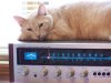
all this hassle- my 525 is being a ... (and I hate cats) LOL :smoke:
 

Attachments

  • 525pussy.jpg
    525pussy.jpg
    75.6 KB · Views: 10
I also wanted to ask that in my noob thinking- does the wz-320 on the schematic mean a 32v zener? Thats what I thought but.. thus the recommendation to step up to a 33v (not down) ?

previous post: correct, a zener is needed. one of those two.

Yes, wz-320 is a 32v 1/2 watt zener diode.

didn't want to complicate things by saying to use two 16v zeners...
I had the choice of 30v or 33v, nothing in between.

zeners are 5% tolerance thus 33v can be anywhere from 31.35 to 34.65
while 30v is 28.5 to 31.5
but the two 16's could be as much as 10 percent off 28.8 to 35.2 ....
 
Rock 'n roll Mark- will try and obtain the 33v and get it in there and post results.

This is Mouser: 512-1N5257B will cost you 6 cents. We charge you almost $7 to ship it...

Digikey wont stock them.

33 and I have been discussing how Radio Shack doesnt even come close to stocking something comparable.

Soo trying to figure out how to obtain a new one that doesnt cost a guy $7...
 
Back
Top Bottom