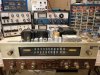
OK, so when is an 800C receiver not an 800C receiver? When it's an 1800 receiver of course, and this bird (serial no 52406 T) just landed on my door step. It is unique with the obvious two-tone face plate, and dual primary winding power transformer that allows for either 120 or 240 volt operation.
Interestingly, this one has a standard Fisher 120 volt (American) power cord that appears to be factory wired in place, and also includes the two standard two-prong accessory outlets on the rear panel as well -- but all references to required operating voltage are absent. Against this however, the silkscreened rating for the fuse on the chassis is given as 1.5A slo-blo, which is basically 1/2 that of the 3.2A slo-blo fuse ratings for standard 120 volt 800C receivers. So, it's a unit that is factory wired for 120 volt operation, and supplied with a conventional power plug set, but has no indication as to what voltage it operates from, and indicates that it requires only a 1.5A fuse. Clearly, the fuse size indication is wrong for 120 volt operation, with a standard 3A slo-blo unit required for that voltage configuration.
And get this: This unit also includes the standard AC line bypass cap connected between one side of the AC line and the chassis, rated for the same voltage as the caps used in an 800C for that purpose, but are made with a ceramic body in place of the typical plastic ones commonly seen. So boy oh boy -- if this baby is wired for 240 volt operation and the plug is inserted so as to have the bypass cap on the hot side of the line, and you get between the chassis and earth ground, then you've just been tasered!!
Beyond these differences, the only other ones I've seen so far include:
1. The use of a bigger AM antenna assembly than those I'm accustomed to seeing on 800C receivers,
2. The negative bias voltage supplied to the output stages has been increased by about 1 volt over that in 800C receivers, and
3. The grid circuit of the MPX relay driver tube is slightly altered.
Otherwise, this is a typical 800C wrapped up in a purty wrapper!
A full recap is on tap plus the addition of a current limiter, and possibly some other work as well, all followed up with a full round of testing to ensure compliance with published specifications. Normally, such a project is pretty routine stuff here on the Fisher Forum, and I normally wouldn't have posted about such a project. But this unit is such a rare bird and so unique in appearance, that I thought folks might be interested in what Fisher did to turn an 800C into an 1800.
Before getting started however, this one's got to take a side trip for repairs, that would almost surely not be corrected by simply recapping the unit -- a scenario I find to occur more often than not anymore.
In performing an initial assessment on the unit, the AM section appears to operate well, but it quickly became apparent that the Stereo Beacon indicator is dead, as is the entire FM tuner section as well -- I mean, no noise from that sucker at all. The former will be easy to chase down, but the latter is showing itself to be the result of multiple issues.
Early diagnosis showed the last limiter stage tube socket was so dirty that the heater was not even lit up in that tube. Some significant coaxing caused it to light, which then brought on the normal FM rushing sound -- albeit somewhat subdued -- but that's all it brought. There was still not a station to be found. Further testing then showed that the second FM IF transformer has major issues (passing only a fraction of the signal it is supposed to causing the weak rushing sound), but even that still should have let me hear my own lab station. But still nothing. The last check then showed no IF signal at all coming out of the RF front end assembly, so that will be the next stop when I pick this back up.
If anything however, this shows why it is always best to fix all the problems noted in an initial assessment first, and then do the recap last. With this unit, the initial assessment still isn't even finished, as the DC output from the selenium rectifier in the DC heater/bias supply is so low, that I've held off even installing the output tubes yet. All testing so far has therefore been done with a scope and signal tracer. Once the current issues noted are resolved, then the assessment can move on to whatever else it might turn up (if anything) until it is finished. Had the recap been done first and then these problems noted (since its a virtual certainty that none of the issues so far are recap related), then you're left stuck trying to figure out what you did wrong, when maybe you didn't do anything wrong at all -- the problems were there to begin with. Or, if you do a good initial assessment, but still dive headlong into doing the recap first hoping it will fix all the ills noted, then you might find out you just recapped an expensive doorstop if the problems aren't resolved by the recap, and they in fact turn into a major $$ pit to resolve. Fixing as you go along and recapping last will produce the least surprises, and get the most done for the least cost.
Pics include:
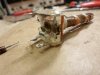
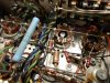
1. A songbird of a different color for sure! And what a neat and unique way for Fisher to start the transition from their vacuum tube gear, into solid state. All the brights appear to be original except for one.
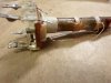
2. The antenna assembly appears bigger than I am used to seeing. The power transformer is physically identical, but includes dual primary windings to allow dual voltage operation. I've never seen a tan colored can insulating cover on the top side of the chassis, either.
3. Underneath, it looks like almost any other 800C you might have seen. Almost.
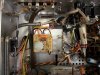
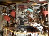
4. Except, look at those very Dynaco like aqua colored caps in the MPX unit. They were standard (stock) on almost all of the small Dynaco amplifiers, but I've never seen them in a Fisher before....... This unit uses the newer encapsulated diode ring detectors.
5. Nor have I ever seen flame-proof power supply dropping resistors in a Fisher before. Must be something to do with international standards.
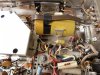
6. The AC bypass caps are basically double the physical size of those used in a standard 800C, but rated at the same voltage. That selenium rectifier has got to go. And look at the different value bias dropping resistors: 8.2K and 27K, versus 5.6K and 15K. The new combination adds about an extra volt of negative bias to the output tubes.
And so a new project begins. More, as there is more to tell!
Dave
Attachments



Last edited: