• The move to the new server is done. There are some software and database maintenance updates in process. This has us passing the hat around to help out. We appreciate any donations. Seriously, even a dollar helps. The payment page may be found here - https://www.audiokarma.org/support.html

1030 mid-resurrection...

vmedia

Active Member
Moving this question off another thread where I was able to get some great help tracking down an issue on a 1030 P700 amp board that was producing sound on the left side only.

Once I was able to get sound out of both channels, I replaced problem preamp transistors and recapped the power supply board.

What I'm dealing with now is some low end distortion on the left channel (I have not fully recapped that side, so I'll hold off to see if the distortion goes away when I've matched the left side of the P700 to the right side)
I will also recap the preamp board. Transistors have been replaced on this board.

The current quandary is I'm not able to adjust the right side bias. It stays low with very little impact when adjusting the VR (R729) on that side (Left side adjusts fine). This is the case whether I'm measuring across one (R747) or both of the resistors. I suspect that this might have something to do with this being cap coupled, but I would expect both sides to act the same. Any advice on how to zero in on what's happening here?
Thank you
 
Register to hide this ad
Double check your soldering and pinouts of the transistors. You should be able to set both sides. Also, check and set your dc balance. Turning that voltage up will cause your bias voltage to drop and turning the dc balance down will cause your bias to rise.
 
Well, sure enough, after checking one of the transistors, I did in fact install it incorrectly. I corrected the mistake and checked all other pin outs and solder connections. I was hopeful this would solve the issue, but unfortunately the right side will not exceed 2.6mv.
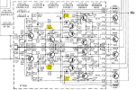
I am skeptical of R729 / R723 . When adjusting both there is a fair amount of jumping around. I have pulled R723 which is marked 31-100k Ohm. Testing shows 0 Ohm to 347K Ohm on one side and 30K Ohm to 340K Ohm on the other side. This seems wrong to me. Thoughts?
Thinking I also should pull and test R729 as well?
Also - I have a fair collection of Bournes VRs - what values are recommended in these positions?
 
Hold it... R723 should be a 100k ohm variable resistor as shown on the schematic. If you pull it off the board and connect it to you DMM set to measure Ohms (black lead on one leg of the VR, red lead on the other leg), it should read 0 Ohms when you turn it all the way one direction and increase to 100k as you turn it all the way to the other direction. I'm not sure what you mean by "31-100k"? You cannot test these VRs while installed on the board. You need to remove them.

I don't know what you mean by "Testing shows 0 Ohm to 347K Ohm on one side and 30K Ohm to 340K Ohm on the other side."?
R729 should be tested the same way, out of circuit, and should read from 0 Ohms to 470 Ohms.

The same applies to the other channel R724 (100k Ohms) and R730 (470 Ohms).

Make sure and mark the current position of the control so you can return it to its original position when you solder it back into the board.
Screenshot 2025-08-19 230459.png
 
Sorry if I confused. I provided more details than necessary. I have replaced R729 and was able to set the bias voltage. Still no joy with the DC setting.
I’ll pull the 470k VR tomorrow test and replace as I have a 500k bournes available (OK to use in place of the 470ohm?)
Thanks.
 
I’ll pull the 470k VR tomorrow test and replace as I have a 500k bournes available (OK to use in place of the 470ohm?)
??? There is no 470k VR on the board, it is either a 100k VR or 470 Ohm VR.
Also, I don't know what VR you replaced R729 with.
Screenshot 2025-08-19 233155.png
R729 = R730 = 470 Ohm... not 470k Ohm
R723 = R724 = 100k Ohm
You cannot use a 500k Ohm to replace a 470 Ohm because the resistance is 1,000x as much so you won't get much range of adjustment.
 
Apologies. It’s late here and I was sloppy in my response (Not good, I know)

I Replaced R723 with a 100k Ohm
And will use a 500 ohm in place of R729 (will test out of circuit first)
More tomorrow, thanks.
 
Been away from the workshop for a bit, but happy to report that everything is working as it should now. The bias setting issue was a combination of old Variable resistors and spotty meter connections. Thanks all for your help!
 
Back
Top Bottom