• The move to the new server is done. There are some software and database maintenance updates in process. This has us passing the hat around to help out. We appreciate any donations. Seriously, even a dollar helps. The payment page may be found here - https://www.audiokarma.org/support.html

1080 protection relay and switch cleaning

TinCanAlley

Duck, you sucker!
Subscriber
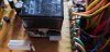
Okay, I'm about to rebuild the protection board in my 1080 and I've always wondered about the one relay with the tape around it. Since I'm about to replace it, I decided to pull the tape off and found what appears to be magnets on either side of the relay, but not sure. What are they? I'm assuming they aren't needed on the replacement relay? I've attached a pic.
20210511_101052.jpg


20210511_101059.jpg

As for switch cleaning, I know you can't disassemble the push button switches in this model, but what is a good way of cleaning them? I've used deoxit and fader lube on them twice over the past couple of years and the two phono switches have to be tapped on a couple of times to make the left channel appear. If I just push it, it usually only comes up with the right channel. Sometimes I have to go back and forth with the switches to finally get both channels out of the phono. There must be some heavy oxidization in there, but without being able to open it, there's not much I can do.
 
Register to hide this ad
The magnets are there to help quench an arc when the relay opens, if there is a large DC offset (amp went to supply rail). I would put them back on the new relay.

I find I can always get the button switches clean. I use a non residue contact cleaner first, then an electronic lubricant after. My secret method is to flatten the spray can straw with a pair of pliers, then inject the cleaner and lubricant into the switch through the opening where the slide enters the switch With the straw flattened it can be slid between coils of the return spring, and placed against the crack between the slide and housing. I raise the front of the receiver so that gravity helps get the chemicals to the back of the switches. This is my "Top Secret" method, so don't tell anyone else:rflmao::rflmao::rflmao:.
 
All the pushbuttons have one or two tiny holes on the top. Just blast the Deoxit into there and work the switches a few dozen times.
 
Any more info on what you are replacing the soft start relay with? I tried to replace it on mine and could never get it to work right.
 
Omron LY2? check the specs against the original. Also check thermal fuse and big resistor. Coil runs off the secondary unregulated DC supply
 
Any more info on what you are replacing the soft start relay with? I tried to replace it on mine and could never get it to work right.

Omron LY2? check the specs against the original. Also check thermal fuse and big resistor. Coil runs off the secondary unregulated DC supply

The soft start relay is problematic, because they do not make a 653-LY1-0-DC48 which is 48v DC, they do still make 653-LY1-0-DC24 which is 24v DC.

The circuit for the 48v relay coil gets +76v Raw DC from pin 19 on the AWR-152 power supply board.Pin 19 is wired to Pin 12 on the Protect board.AWM-120. then to the relay, R12 a 2200 ohm 2 watt resistor. connected to pin 11, which is externally grounded. 2200 ohms soaks up the extra 28 volts dissipating it as .356 watts of heat. Dropping to a 24v relay means 52 volts at twice the current , maybe too much of a load for the 76v supply.

Any change in relay coil voltage means a different resistor must be calculated and used. OR a different source for the voltage must be found,

There IS a raw +24v DC available, that pin 19 can be isolated from the +76v feed, and connected to the +24v. In THAT case, R12 has to go to zero ohms.

One cut on the power supply pc board, and a new connection made.

upload_2021-5-11_19-7-6.png
 
Last edited:
The magnets are there to help quench an arc when the relay opens, if there is a large DC offset (amp went to supply rail). I would put them back on the new relay.

I find I can always get the button switches clean. I use a non residue contact cleaner first, then an electronic lubricant after. My secret method is to flatten the spray can straw with a pair of pliers, then inject the cleaner and lubricant into the switch through the opening where the slide enters the switch With the straw flattened it can be slid between coils of the return spring, and placed against the crack between the slide and housing. I raise the front of the receiver so that gravity helps get the chemicals to the back of the switches. This is my "Top Secret" method, so don't tell anyone else:rflmao::rflmao::rflmao:.

I'll try flattening the tip a bit. I've cleaned these things 3 times now. I've even tipped it up on its back so it would be pulled through the switch by gravity. I don't know enough about the inside of them to know if it could be more than just corrosion.
 
Any more info on what you are replacing the soft start relay with? I tried to replace it on mine and could never get it to work right.
I order this: MY2-02-DC48 Omron General Purpose Relay

It was recommended for the 1080. I'm hoping it works, if not, I have the original. It isn't the soft start that is giving me problems.
 
Okay, I'd rather ask a stupid question than mess something up. So I did the caps and transistors on the protection board and am looking at the relays. The replacement relay for the protection has 6 soldered legs and the replacement has 8. The spacing of the legs point to the last set going as it wouldn't match up with the PCB holes otherwise. So am I correct? Just cut off the last 2 legs and be done with it? o_O
 
Okay, I'd rather ask a stupid question than mess something up. So I did the caps and transistors on the protection board and am looking at the relays. The replacement relay for the protection has 6 soldered legs and the replacement has 8. The spacing of the legs point to the last set going as it wouldn't match up with the PCB holes otherwise. So am I correct? Just cut off the last 2 legs and be done with it? o_O

Yes, Those two contacts are the normally closed contacts of the relay, and are not used.
 
Okay, I have done the caps and transistors and decided to test before I started the relays. Now when I turn it on, it takes 51 seconds to hear the relay click and the speakers come on. I've tried a number of times and it is pretty consistent. I check the base of the transistor and before the relay, the voltage is 0. Once the relay kicks in, it is .7.

Also, the caps and transistor replacements did nothing for the FM indicator flashing when the relay click on power down. The clicking relay is the softstart, so I don't know what is happening upon the power down that causes the relay to click and the FM indicator to flash.

I don't want to mess with the relays until I understand what is going wrong, unless it turns out the relays are why things are going wrong. However, I don't think a relay could cause the major startup delay of 51 seconds.
 
I just went over all the voltages on the protection board and compared to SM. They are as expected. Only thing, to measure the .7 for Q2, I had to wait the 51 seconds for the relay to click, then I found voltage. Could it be the (tested before install) C3 is bad? My understanding is that cap is responsible for the amount of time it takes to reach voltage for Q2 to trigger the relay.
 
Boy, do I feel stupid. Somehow a 470/25 made it into my bag of 47/25 caps. So I can see why it is taking so long since it has to be charged before triggering the relay. Time to swap it for the correct one.

That takes care of the startup time, so now I just need to know why the FM indicator flashes on shutdown. I haven't replace the relay yet, but want to fix the issue before installing the new relay. That is, of course, unless the issue is the relay.
 
Well, as I expected, since the 470 is ten times larger than the 47, the time would be reduced that amount. It now takes 5 seconds. And what I also noticed is the soft start relay is so much louder than the protection. Even up close you can barely hear the protection with the soft start being so loud. And during shutdown it is even louder.
 
Back
Top Bottom