• The move to the new server is done. There are some software and database maintenance updates in process. This has us passing the hat around to help out. We appreciate any donations. Seriously, even a dollar helps. The payment page may be found here - https://www.audiokarma.org/support.html

120 Cylcle Hum After Recap - AKAI AA-6600 - Next steps?

JB8

Well-Known Member
Team Audiokarma,

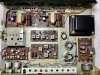
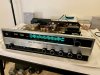
I recently found this dude, likely paid too much for it but love the look and the wood case. Trying to tackle the 120 cycle hum I'm getting out of both channel across all functions and with volume at zero.

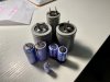
Welp, I replaced a bunch of caps because, well, I wanted to! This is an old unit and my wife actually bought me a Hekko desoldering gun for X-mas, and I love the process (I can hear the throngs of people saying the caps didn't need to arbitrarily be replaced, but due to the age of the unit it's still a good idea based on the average life of a capacitor. BTW, they all tested well out of spec once removed.) Safe to say the unit sounds stronger and punchier but damn it, that hum is still hanging out.

Disclaimer: The zip tie suspension system on the main filter caps may not be sustainable, but in the moment it sounded fun, so hopefully this isn't a dangerous solution for the time being.

I know there have been a number of threads on this, hoping someone has some experience with vintage AKAI receivers, any help is appreciated.

Btw, I checked for functionality between each section during the recapping and the hum did not get worse. Hum frequency was measured with a free app, locked in at 120 cycles during multiple tests.

Lastly, I did go around much of the board trying to make sure all the screws were snugged up, did not have a loose one in the bunch.

Just point me in the right direction, happy to learn how to track down a bad ground, or what ever you feel it may be due to. (by the way, not working on the unit tonight, it's IPA night....)

Thanks in advance!
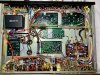
IMG_8430.jpg IMG_8431.jpg IMG_8432.jpg IMG_8434.jpg IMG_8433.jpg
 
Last edited:
Register to hide this ad
What voltages are you seeing on pins 1,2,3 & 4 on the power supply board ?
 
Hakko! What the hecko... Damned IPA's

I can swap out a cap but this is my first time recording voltages for a power supply. You've helped me out before, @avionic, would really appreciate your guidance here.

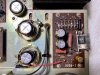
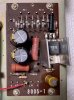
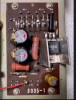
From the three pics below perhaps you can head me in the right direction. Assuming I need to keep the one test lead grounded, then with great care, touch the positive test lead to each pin and record the voltages?

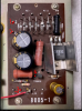
AKAI AA-6600 Power Supply I.png AKAI AA-6600 Power Supply II.jpg AKAI AA-6600 Power Supply III.jpg
 
Appears that you've got the orientation on one of the main caps wrong. Did you take any pix before
starting work (cap should have exploded?). Will try and work out which.
upload_2021-6-12_16-30-51.png
 
Good afternoon, @mbz, thanks for jumping in!

Here's a before pic, I distinctly marked the neg. sides and you can see my marks on the chassis showing which side the negative sides from the original caps were facing. I thought it was strange too but have read countless times that you should trust the way it was wired and just hope that it's correct. Since the hum hasn't changed throughout the process, even with adding some 8 new caps, and the music is pumping when I push the unit a bit, I'm assuming these are installed correctly but I could be wrong. Happy to check the voltages as well, just need to know which to test. Thanks again!

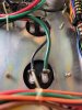
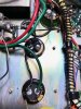
Filter Caps I.jpg Filter Caps II.jpg
 
Nah, think I made a mistake, confusing with the main filter caps. What are the uf/V of those 2 large caps.
 
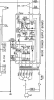
I need to step out. Try measuring dc voltage at the 4 points below ie, 3 solder blobs and emitter leg of TR802. Measure each
in turn with black probe connected to chassis/GND.
upload_2021-6-12_16-57-16.png
 
Alrighty! Cracking on again!

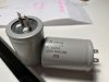
First, the uF/V of the main filter caps is 3300/35 and I replaced them with the same value. For the power supply pair, 220uF 50V, and also replaced with the same - no upgrades for the 8 I replaced, just went like for like.

Thanks for identifying the voltage points, here they are:

1) +B = 35.90 V
2) -B = 36.21 V
3) +B = 44.92 V
4) TR802 Emitter Leg = 12.46 V​
 
Last edited:
Did you make sure to wire the new capacitors like the old one's in post #7?

The positive of one capacitor goes to the negative of the other capacitor.
 
Did you make sure to wire the new capacitors like the old one's in post #7?

The positive of one capacitor goes to the negative of the other capacitor.

I did, even drew a diagram to have as a reference before I started to remove the old caps. Tested the unit each time I changed a pair out to make sure it wasn't getting worse, and wore eye protection just in case, no change so far. But damn, when you turn up the volume above the hum this things is clear, strong and punchy - if we can kill the hum it will be a keeper for sure!

Filter Caps I.jpg Filter Caps III.jpg
 
Yessir, was hoping the recap would fix things, plus due to the age of the unit it seemed appropriate, but here we are still chasing that 120 cycle hum (all of the caps I replaced tested well out of spec once I had them out of the unit, so even if some were still marginal and functioning I had fun swapping them out nonetheless).

I'm actually excited to continue the troubleshooting on this in spite of all the threads and YouTube video's cautioning that's it can be a needle in a haystack at times...

Did the voltages I posted help with the diagnosis?
 
The voltages are probably fine. A schematic will tell.

As Avionic stated, I would be concentrating on the power supply board.
 
An oscilloscope is more useful in tracking down hum problems because you get a visual indication
of the source of the problem. Anyone serious about component level repair should have a scope.
On the other hand, If you replace enough parts, You'll also eventually fix it. I prefer the former method.
Also helps to have a basic working knowledge of electronics 101.
 
Thanks, @regore, that's what I love about this forum - lots of great suggestions along with gentle reminders that there's a differentiation between serious repair folks and hobbyists like myself.

Learning with each unit I work on, eventually I'll get to the 101 level, in the meantime I hope I'm not insulting anyone with my remedial approach, ha! Have to start somewhere, right?!?

An oscilloscope would be awesome, hope to get one some day. And for this unit, I'll just keep chipping away!
 
Service manual voltages are +/-30, +27.5 and +12Vdc.
TP3 +44.92V is the standout, maybe TR801 c-e short?
TP3 appears to be for stereo lamp... also feed TR802b.

Suggest diode check TR802 amp powered off.
 
Concentrating on the power supply board, I swapped out the C458 (TR802), this did not change the hum but it did result in some transient static in the left channel that has since subsided. Made sure the pinout was accurate when installing the KSC1845F.

Something I neglected to mention is that there's no stereo separation and the light doesn't come on when tuning in FM stations I know to be in fine stereo. I tested the light and it worked, but I'm curious what the voltage should be on the point called IND (left side in pic). It measures at ~45 V, is that where it should be? Again, if I'm focusing solely on the PS to challenge the hum it seems like this could be one of the players based on it's location. If not, all good, just want to rule things out.

If my voltages in general are acceptable, is there a hierarchy of components to tackle one at a time or should I just start making a list of parts and essentially rebuild the entire power supply board?

Thanks again, no hurry, appreciate everyones time and patience.

PS TR802.jpg

PS: I have the unit running and the 120 cycle is just humming along, but when I put on The Cars Candy-O album playing through the computer, there was a song in the same general key and it produced some awesome phase oscillation in the room, bonus!
 
Back
Top Bottom