• The move to the new server is done. There are some software and database maintenance updates in process. This has us passing the hat around to help out. We appreciate any donations. Seriously, even a dollar helps. The payment page may be found here - https://www.audiokarma.org/support.html

120 Cylcle Hum After Recap - AKAI AA-6600 - Next steps?

Thanks, @mbz, I think we were writing our replies at the same time, nice to see we're heading down the same path!

For TR801, what should I expect to see when checking for the short across c-e, and can I just check with it installed or is it best to pull it to test?

More electronics 101, but damned this is fun!
 
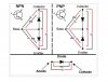
Nice graphic from markthefixer on diode testing a transistor. red/black indicates mm probe orientation.
Either 640mV(approx) or OL(open loop) expected. Use diode function on mm. You can do the c-e test
in circuit.
DiodeTest.JPG
 
Thanks, @mbz, the chart is fantastic, great resource @markthefixer!

When testing across C-E in Diode Mode, regardless of test lead orientation, I'm getting aloud beep, a red light and a reading of 0.000, guessing this means it's bad? If that's the visual, and audible for, "hey, this thing is working great" I'd be shocked...

If this is the culprit it's an easy fix once I find a replacement. The schematic has this listed as a 2SC932, but the actual part number is listed as 2SC931E (41) - assuming the two are interchangeable (?), I'm looking at the NTE186 as a replacement, am I on the right path or is there a better/more suitable option? In a different AK thread kevzep suggests the KSC1674 as the best option for 2CS930, but its BJT - would either configuration work, assuming I need to stick with the FET that's currently installed along with the heat sink?

If theres a specific replacement most people use here I've already got DigiKey ready to go, would love to order this puppy and get it installed ASAP!

DIODE MODE.jpg
 
120Hz hum almost has to be something directly connected to the main filter caps, as that is where the AC is removed. Check the AC voltage at the plus and minus rail points on the main caps -- more than a few mV is a problem. Check your ground connection at the main filter caps, and make sure you have exactly duplicated the original wire configuration -- it matters where the wires are soldered on. If the ground wire for other parts of the power supply is attached BETWEEN the center point of the capacitors and the chassis ground point, you can broadcast the ripple on the main filters all through the power supply and amplifiers. Ground for anything other than the filter caps must be attached on the other side of the ground point.

The other source is a very leaky diode in the rectifier -- did you replace the rectifier diodes? If not, I would. Usually a leaky one will give you 60 Hz hum I think, though as the rectified voltage will have a "stagger" with one wave higher voltage than the other. Rectifier diodes are inexpensive, and faster lower noise ones are available.

You should also verify all ground points on the schematic and check any ground connections to the chassis, either wire or screw connection. Screw connections often have solder pads on the board, and if they are worn away or dirty you won't get a good ground. If you have a bad ground somewhere, you can get a "ground loop" where the ground is through some other part of the circuit. A wire broken inside the insulation or a corroded wire wrap can cause a "flying ground" or an indirect ground through some part of the circuit instead of direct.

 
  • Like
Reactions: JB8
Certainly follow up on suggestions of others (diodes etc...)
2SC931 looks faulty, c-e short, should be removed and retested out of circuit (didn't see alternate paths for short).
Not much luck finding a sub, npn, Ic=3A, cbe
 
  • Like
Reactions: JB8
Thanks, All, for the suggestions, feels like we're gaining some traction here.

For the rectifier diodes, (thanks, @avionic), can they be tested in circuit and what kind of reading should I be looking for? Sounds like I should just replace them but still wondering about diagnostic options.

I'm keen on replacing the bad transistor once a replacement has been identified, so if I change out the rectifier diodes as well at least the power supply will be almost completely rebuilt, sweet! If these changes don't fix it I'll dig deeper into the grounding and keep going until I find it.
 
Found an AK thread on a different AA-6600 from 2015 where @blhagstrom mentioned that the MJE3055T is a great replacement for the 2SC932, does this still jive or are there others that should be considered over the 3055? They're readily available so I'll likely just snag them and the diodes then wait patiently for the shipment to arrive... Knowing full well the problem may still exist, but eager to trudge on!
 
Excellent, thank you. I'll get on with it and post an update later next week, no more bloviating, for now!
 
I HAVE had a leaky regulator cause 120 Hz hum, especially if the amplifier otherwise performs satisfactorily. The 44 volts is way high and that's a clue to a bad regulator, too. Check that out. The regulator for the low voltage supply to circuits.

Doug
 
UPDATE:

Replacing TR-801 did the trick, no more hum! Still not getting the stereo light to come on and not hearing any separation, FM mute isn't responding to adjustments, so I'll keep trying to connect the dots. That said, getting rid of that hum was a great win, due to your counsel, thank you!

When swapping out the 2SC932 for the new MJE3055T I could hear all of you chanting in the background "check the pinout, check the pinout, check the damn pinout, dude!" At first I had the leads matched up, like for like, then heard your voice, and rerouted C and B, and bam, worked like a charm. After replacing all the caps on the power supply, amp and the filter caps this thing has some juice, so the rest of the little fixes will only add to how tight the sound is now.

Based on the title of this thread I guess we're at the end here, but I welcome any suggestions on the stereo action if anyone is eager to help, otherwise, cheers and thanks again. :rockon:

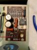
IMG_8575.jpg IMG_8579.jpg
 
Ahh what the heck, may as well toss out some details around the FM issue, right?

Testing at TR802 I'm getting the following DC V readings:

E = 12.6 V
B = ~35 V
C = ~35 V

Also getting that ~35 DC V at TR304 on the collector only, showing no voltage on E & B of TR304 when tuned into a stereo station with power on of course.

Any advice is much appreciated!

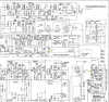
AA-6600 Schem..png AA-6600.jpg
 
Back
Top Bottom