• The move to the new server is done. There are some software and database maintenance updates in process. This has us passing the hat around to help out. We appreciate any donations. Seriously, even a dollar helps. The payment page may be found here - https://www.audiokarma.org/support.html

1961 Motorola Console SK56MB-1A Rebuild

Eric Butler

New Member
Hi All,
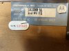
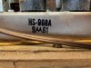
I am new to the forum and hope this is the right one to post this to. I just wanted to say hello and talk about the rebuild I am planning/doing on a 1961 Motorola console with a 3 channel HS968A amp, HS969A pre-amp, HS-996 FM stereo adaptor and record player. I was able to get the schematics from radiomusem.org and have been going over them for a bit. I am a technician and am used to working on semiconductor equipment as well as radar and sonar gear in the Navy, so I am aware of the lethal hazards in working on this type of equipment. With that being said, its been a while since I worked on component level stuff other than a power supply here and there, but I definitely respect the nature of hazardous voltages when I work on things. Digging into the schematics and a few YouTube videos have refreshed me as to the signal paths and workings of this type of push-pull amp and I have a good feel for going about things.
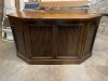
The cabinet itself is a beautiful Mahogany console. It does not have the usual look of the stereo consoles, which, to be honest, I prefer. I did plug it in and test the functions to see where it stands and the sound was unbelievable. Yes, I know now that that was bad. It has the Vibrasonic System which drives what looks to be a "15 woofer, but that channel was not working. Other than that, everything else worked. I also plugged in a Topping E30 DAC with 24bit/96khz stream into the tape input and it was fantastic. Both right and left channels worked and sounded even. There was only a very light hum with no input at 2 on the dial.
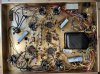
For the amp, my plan is to re-cap and replace the resistors and the circuit breaker first, add some banana clips for the inputs & outputs, add a separate power switch. When that's done, I will take a break, enjoy it for a bit and move on to the pre-amp. So far, I only removed the amp, labeled everything and checked the resistors on the amp and they all have migrated up in, that is why I am going to replace the resistors. My cap tester is arriving today, but I plan to replace them all any way, so I guess I could have waited on that.
The amp's tubes seemed to mostly be original tubes (Motorola) and only have 2 replacements, which are RCA's, One of the power tubes, a 6V6GTA, and one of the Amp & Inverter tubes, a 12AX7A. But like a dummy, I did not label them when I removed them. Luckily, I took a ton of pictures and know they were both from the Left channel. but that still leaves me with the bad Vibrasonic channel that could be a tube and now due to stupidity I threw in more troubleshooting and matching. I won't do that again.
There is a can with three 40MFD/400W and a 200MFD/50W that I am going to replace, but I am not sure if I want to re-pack or try to put underneath. There does not seem to be enough room, but after looking a bit, I may be able to find the room. Will have to see when I get the replacements.
I wanted to get this on the forum and am open to any questions, advice or suggestions. The grand plan is to refurb the entire thing and put in the dining room, but if/when the amp gets going I will likely take a breather and enjoy that for a bit. I do plan to do more of this, so I want to get decent test gear, I don't want cheap, but don't want to spend a ton.

Some questions I have:
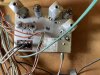
What is the lamp module? It is located in the right speaker area. Guessing it is what it says.
What resistors are best to use for around the tubes?
I do not see many of these amps on the internet, how were they?
Does anyone have one of these or experience with them?
Should I get a Variac?
What test gear should I get at a reasonable price?

Thanks for getting down to here, sorry for the long write up.

Regards,
Eric
 

Attachments

  • Lamp module.jpeg
    Lamp module.jpeg
    114.1 KB · Views: 125
  • Model.jpeg
    Model.jpeg
    121.3 KB · Views: 122
  • Amp in unit.jpeg
    Amp in unit.jpeg
    126.2 KB · Views: 127
  • Amp bottom.jpeg
    Amp bottom.jpeg
    196.1 KB · Views: 123
  • FM stereo module.jpeg
    FM stereo module.jpeg
    146.7 KB · Views: 120
  • pre-amp.jpeg
    pre-amp.jpeg
    125.4 KB · Views: 119
  • IMG_0133.jpeg
    IMG_0133.jpeg
    127.4 KB · Views: 116
  • Tuner.jpeg
    Tuner.jpeg
    132.2 KB · Views: 121
  • Console front.jpeg
    Console front.jpeg
    131.9 KB · Views: 126
Register to hide this ad
I'm guessing the lamp module has something to do with the reverb unit, but thats just a guess without a schematic. Sometimes lamps are used for their non-linear resistance curves to get some specific job done. I have an HP VTVM that uses a set of 4 of possibly that same lamp in some sort of auto-balance circuit to make it more stable.

for resistors, 1/2 watt metal or carbon film are fine. Both are common and better than the old carbon comp resistors. They are less noisy and hold value better with age and heat. I tend to shop by "cheapest first" so I won't preach any particular brand. I do go for the physically larger ones though. They are rated for higher voltage but more importantly don't look as silly in an old amp.
 
Welcome!

The 15 inch speaker is actually the bass channel. The vibrasonic should have it's own 3 or 5 inch speaker. A picture shot of the speakers should confirm this.

You have the top line 30 watt 3 channel amp. Two 6V6's in push pull for the left and right mid/hi channels and two 6V6's in push pull for the bass channel.

Basically you would only need to replace the can capacitor. The disc types seem to last forever. You can replace them but in my personal opinion and experience, it's not really necessary.

Two 6V6's in push pull is good for about 10 watts so 3 pairs is good for about 30 watts.

No need to replace the resistors unless they read high or are open.
 
Last edited:
I'm guessing the lamp module has something to do with the reverb unit, but thats just a guess without a schematic. Sometimes lamps are used for their non-linear resistance curves to get some specific job done. I have an HP VTVM that uses a set of 4 of possibly that same lamp in some sort of auto-balance circuit to make it more stable.

for resistors, 1/2 watt metal or carbon film are fine. Both are common and better than the old carbon comp resistors. They are less noisy and hold value better with age and heat. I tend to shop by "cheapest first" so I won't preach any particular brand. I do go for the physically larger ones though. They are rated for higher voltage but more importantly don't look as silly in an old amp.

Thanks for info! I think your right about the lamps. After wire tracing it seems to be the case. I just can’t see it on the schematics. I think I am going to hold off on resistors since they seem to be in the +- 20%.
 
Welcome!

The 15 inch speaker is actually the bass channel. The vibrasonic should have it's own 3 or 5 inch speaker. A picture shot of the speakers should confirm this.

You have the top line 30 watt 3 channel amp. Two 6V6's in push pull for the left and right mid/hi channels and two 6V6's in push pull for the bass channel.

Basically you would only need to replace the can capacitor. The disc types seem to last forever. You can replace them but in my personal opinion and experience, it's not really necessary.

Two 6V6's in push pull is good for about 10 watts so 3 pairs is good for about 30 watts.

No need to replace the resistors unless they read high or are open.

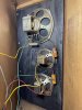
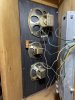
Thanks for the great info. You are right about the vibrasonic. It looks to have its own speakers! As per your advice, I’m going to replace the can capacitors. Here’s some pics of the speaker wells. Thanks.
 

Attachments

  • EC81031F-FBD3-430C-9400-6B080FD905DC.jpeg
    EC81031F-FBD3-430C-9400-6B080FD905DC.jpeg
    147.6 KB · Views: 52
  • A6922802-858D-4833-951A-5FD173760D7D.jpeg
    A6922802-858D-4833-951A-5FD173760D7D.jpeg
    135.4 KB · Views: 50
Hi All,
Just an update. The electrolytical caps were ordered and I should get them this week for both the amp and pre-amp. The pre-amp is still in the console, so the plan is to remove it during the week. Soldered some speaker wires onto the outputs to hook up external speakers as well as separating the amp from the pre-amp with a jumper and when tested, the hum that was previously there is gone. My soldering skills need some practice and I was using 12 gauge wire, which made things a little tougher. It really sounds beautiful, such detail, its amazing. Getting some Banana plugs and going to make a external speaker switch ultimately.
A few questions:
With it being separated, the Left/right is being used, but I do not have an input for the Bass/Vibrasonic channel. Is it ok to remove the tubes for now and run with just the two channels. I would think it would be ok, but wanted to ask you all, since I am not 100% about wether the load on this channel matters when its not in use?
Should I troubleshoot the pre-amp prior to replacing all the electrolytical caps? I am leaning towards yes, so I can know why it was humming vs the shotgun approach of replacing all the caps and not knowing where the issue was that caused it, if it was due to a cap.
Do I need to have speakers hooked up to it? I think I read somewhere not to turn on a tube amp without the speakers plugged in.

Thanks for the comments from the first post. Being new to this, they helped me figure out a good path with your experience. The Vibrasonic definitely uses the bulbs. The schematic shows the signal running thru a bunch of inductors. I am going to go after that later on, after I clear up some of the other issues. I looked thru the Motorola thread and it was nice to see. Going to get some pics up there once I get done with the refurb. Doing some research, this is a really nice console and I am looking forward to getting it back into shape.

All comments are greatly appreciated, thanks in advance!

Regards,
Eric
 
Why would you want to disconnect the bass channel? With these 3 channel amps, the only bass being produced is through the center bass speaker. The left & right speakers don't produce any bass, just the mids & highs. They are not full range.

Also, the bass channel is connected using the left & right speaker outputs via a crossover network in the amp itself so the center channel needs to remain plugged into the main amp.

I think you can just disconnect the vibrosonic module/amp from the main power if you don't want it in the mix. All the tubes can remain in it, they just won't be lit so you will not get any sound through the vibrasonic speakers.
 
Last edited:
Why would you want to disconnect the bass channel?

Also, the bass channel is connected using the left & right speaker outputs via a crossover network in the amp itself so the center channel needs to remain plugged into the main amp.

I think you can just disconnect the vibrosonic module/amp from the main power if you don't want it in the mix. All the tubes can remain in it, they just won't be lit so you will not get any sound through the vibrasonic speakers.
Why would you want to disconnect the bass channel? With these 3 channel amps, the only bass being produced is through the center bass speaker. The left & right speakers don't produce any bass, just the mids & highs. They are not full range.

Also, the bass channel is connected using the left & right speaker outputs via a crossover network in the amp itself so the center channel needs to remain plugged into the main amp.

I think you can just disconnect the vibrosonic module/amp from the main power if you don't want it in the mix. All the tubes can remain in it, they just won't be lit so you will not get any sound through the vibrasonic speakers.

Thanks for feedback. Right now, I disconnected the Amp from the Pre-amp and I am using external speakers. The amp has 3 inputs/output channels (Left/Right/Vibrasonic). So, I don’t have anything to input into the 3rd channel. The Vibrasonic pre-amp circuitry is in the pre amp which is still in console and the Vibrasonic module is just a bunch of inductors, also still in the console.

Eric
 
shouldn't need the vibrasonic input, but you do want the center channel output. The L and R are combined and fed through a low pass into the bass amp. They are run through a high pass into the L and R amps, so without the center channel it has no bottom end.
 
This is what I was trying to say. You won't have any bass without the center channel no matter what external speakers you use. Like Gadget says, you won't get any bottom end.:no:

These Motorola's are not your typical standard 2 channel stereo amplifiers. :no:

Are you saying that you are wanting to use the amp by itself as a stereo amp? This is not a stereo amplifier.:no:

Your best bet is to use this console as intended as a single unit with everything connected together as designed.:thumbsup:

I think that only Motorola and a couple of other manufacturers like RCA and Philco made some 3 channel consoles for a short time but you don't see too many of them as they probably weren't very popular in the day. :idea:

I also own a 3 channel Motorola console (minus the vibrasonic feature) and I have it refurbed and use it as originally designed.
 
or you can use an orphan speaker that has a decent size woofer and run it as a 2.1 setup. That would be legal.
 
This is what I was trying to say. You won't have any bass without the center channel no matter what external speakers you use. Like Gadget says, you won't get any bottom end.:no:

These Motorola's are not your typical standard 2 channel stereo amplifiers. :no:

Are you saying that you are wanting to use the amp by itself as a stereo amp? This is not a stereo amplifier.:no:

Your best bet is to use this console as intended as a single unit with everything connected together as designed.:thumbsup:

I think that only Motorola and a couple of other manufacturers like RCA and Philco made some 3 channel consoles for a short time but you don't see too many of them as they probably weren't very popular in the day. :idea:

I also own a 3 channel Motorola console (minus the vibrasonic feature) and I have it refurbed and use it as originally designed.

The more I
This is what I was trying to say. You won't have any bass without the center channel no matter what external speakers you use. Like Gadget says, you won't get any bottom end.:no:

These Motorola's are not your typical standard 2 channel stereo amplifiers. :no:

Are you saying that you are wanting to use the amp by itself as a stereo amp? This is not a stereo amplifier.:no:

Your best bet is to use this console as intended as a single unit with everything connected together as designed.:thumbsup:

I think that only Motorola and a couple of other manufacturers like RCA and Philco made some 3 channel consoles for a short time but you don't see too many of them as they probably weren't very popular in the day. :idea:

I also own a 3 channel Motorola console (minus the vibrasonic feature) and I have it refurbed and use it as originally designed.

Thanks for that explanation. This is what I like about this stuff. It is getting clearer, the more I learn about things. Going over the schematics, I did not quite get it, but this makes so much more sense now with the 3 channels (or 2.1). It was just ahead of its time in a way. So, the full restore is definitely the only course to take.

Thanks,
Eric
 
Anything to report? I'm going to look at one of these in a few days. I like @gadget73 's idea (as I typically do) of running it as a 2.1, whether inside the console or not. Did you decide to restore the console and keep it intact? I think I'm more inclined to want to gut the console. Not much demand for consoles these days if I want to sell it at some point. I'm also inclined to gut the circuitry, make the L/R channels full range, and keep the center channel with a low pass, although maybe lower as appropriate for a subwoofer.

And you mentioned schematics. Any chance you could share those or point me to where you got them?
 
only possible hitch with it, the crossover point is quite possibly high enough that the ".1" speaker needs to be basically in the middle to make it not sound odd. Sound starts getting noticeably directional over 200hz or so.
 
only possible hitch with it, the crossover point is quite possibly high enough that the ".1" speaker needs to be basically in the middle to make it not sound odd. Sound starts getting noticeably directional over 200hz or so.
Any particular reason not to make the crossover lower, like where Klipsch bookshelf speakers tend to bottom out? (I don't know the typical values for those lower ends off the top of my head. Somewhere around 100 Hz?) I would imagine that many or all of the interstage blocking caps, and cathode bypass caps, would need different values for all the channels?
 
Any particular reason not to make the crossover lower, like where Klipsch bookshelf speakers tend to bottom out? (I don't know the typical values for those lower ends off the top of my head. Somewhere around 100 Hz?) I would imagine that many or all of the interstage blocking caps, and cathode bypass caps, would need different values for all the channels?

limitations in the L and R channels probably. I suspect they just can't go low enough to allow the center to be used as a sub. Thats probably more a transformer limitation than anything easily changed.
 
limitations in the L and R channels probably. I suspect they just can't go low enough to allow the center to be used as a sub. Thats probably more a transformer limitation than anything easily changed.
You mean I would need MORE METAL? Sorry, listening to Black Sabbath ...
How do the OPTs on these Motorolas compare with those on the Magnavox 175/185? Stock OPTs on those are pretty wimpy. Wimpier still on the Motorola? I have to admit that I don't understand the relationship between output power and the size of the OPT. If I consider first principals, with a larger OPT, it could have fewer turns in the secondary, thus higher amplitude voltage on the output, and handle the greater current that would result without burning up. Do I have that at least approximately right. If so, can you increase output power simply by switching bigger iron and leaving the rest of the amplifier circuit unchanged? It couldn't be that simple. Any recommended reading on this subject?
 
Back
Top Bottom