• The move to the new server is done. There are some software and database maintenance updates in process. This has us passing the hat around to help out. We appreciate any donations. Seriously, even a dollar helps. The payment page may be found here - https://www.audiokarma.org/support.html

2-way with ess heil amt

Also note that the woofer passband is around 93dB, but at 2KHz it peaks to 105 dB,
that's over 10dB. The RC network across the woofer inductor, if done right provides
a notch in the XO to help tame that peak. This is a different peak from the previous
one mentioned.
the 15" GRS woofer im working with or the 12" you spoke of?

as far as the 2 way we're discussing, with a , wouldnt the -12dB/octave slope at 1.2K tame that peak?
 
the 15" GRS woofer im working with or the 12" you spoke of?
Shown for the 15PT in post number 4 of this thread.
Note, however that as you go off axis the peaking is reduced, so the amount of compensation
will depend on how you place the speakers. If the woofer is mounted low, not at ear level
then listeners will be off axis in the vertical direction. If not toed in then also off axis in the
horizontal direction. The on axis peak is over 10 dB but you might only need a 3dB notch, it
depends. I expect that these will sound best toed in, so I'd plan for that.
 
thank you for your repsonses.
is there a problem with crossing over at 1.2kHz?
its a common crossover point for the AMts and well withing the GRS performance capabilities
1.2 KHz is fine, just scale Earl's cap larger by 1.5/1.2, that should get you in the ball park.
PE provides .frd files for these drivers so the XO could be simulated.
Where did you get the Heil XO design, is it from one of their designs?
I think that 3rd order is good.
 
the 15" GRS woofer im working with or the 12" you spoke of?

as far as the 2 way we're discussing, with a , wouldnt the -12dB/octave slope at 1.2K tame that peak?
For that 2nd order to behave like a second order you need the driver to be flat, more
often, the woofer has its own 2nd order rolloff so combined you get a roughly 4th order
response - it depends. If the peak in the woofer response is real it will throw things off,
so I'd try to notch it by 3-8 dB. Depends on woofer placement and how it actually measures.
 
Now also note looking at the 15PT FR that it ramps up from 1 KHz to the peak at 2KHz.
If you want a 1.2 KHz XO you might need to scale it back to 900 or 1K to start it early
to compensate for the slow rise, then you may or might not also need a notch to knock
down the 2 KHz peak.
I would say that crossovers designed without measurements are most often doomed to
failure. BUT, if you have a known good XO for the Heil, and 3mH is about right for the
woofer inductor, then your variable is the cap, try different values, and the notch if needed.
 
1.2 KHz is fine, just scale Earl's cap larger by 1.5/1.2, that should get you in the ball park.
gotcha
PE provides .frd files for these drivers so the XO could be simulated.
i dont know how to sim. maybe ill find someone to sim for me.
Where did you get the Heil XO design, is it from one of their designs?
I think that 3rd order is good.
ess recommends or uses 18dB/octave
 
Is there a "best" ESS model with a good 3rd order network at 1.2K? Where did you get yours?
Also, do they wire the drivers in phase or?
 
I suggest that you look at the 12PT spec sheet and you'll see that the impedance
and FR are very similar. Also note that Earl states that he averaged several of the
off axis curves for the .FRD that he used.
 
When a woofer is crossed high say around or above 1 KHz and it has high inductance
you'll see a peak (often large like 5-10 dB) before rolloff in the electrical response of the
XO as loaded by the woofer. I've simply added a 20W large resistor (27-33) ohms across
the woofer to save on an additional cap and it often works.
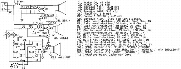
Depending on the woofer, doesn't even have to be that high of a frequency. It's just based on the crossover point. Note the combined values of R1 (i.e., 28.1 ohms). I found the value to be very critical and to really get it right, you must be within a fraction of an ohm. Above 30 and lower midrange got peaky. Below 27 and low bass got boomy and lost detail. The crossover is a second order low pass at ~230 Hz. Also note R5 and 6 which do this for the 2251 but in this case it is more about glare.


80-2026_03_31_14_06_03_101b01ce701a6fe5e2aa9f219cd89f862f68ec33.jpg
 
Last edited:
Is there a "best" ESS model with a good 3rd order network at 1.2K?
i bought the pair for $250 new, and i studied data shets and crossovers, but i dont kno what the best speaker model. id imagine the best amt heil driver is the full size.
Where did you get yours?
ESS
Also, do they wire the drivers in phase or?
its one driver, and...i do not know whats in/out phase yet. theyre wired light blue and pink IIRC. their website doesnt have much readily accessible information.
I suggest that you look at the 12PT spec sheet and you'll see that the impedance
and FR are very similar. Also note that Earl states that he averaged several of the
off axis curves for the .FRD that he used.
cool.

they are very similar, but the 15" is double the cone mass, starts baming way earlier, and is shouts a few dB louder as the frequency increases. i figure its not a bad thing to make it behave like an 8 ohm woofer in stead of a 17 ohm--ist this what the zobel is for?

please excuse my not fully understanding--i am very new to speakers other than using em. i made an open baffle speaker and thats it.


i just upped L1 to 3.9mH and C1 to 15.6uF for baffle compensation. the way i understand the inductor has to lean on the lower mids and mids to match the low end. is that about right?
 
Last edited:
My question was where did you get the Heil XO schematic, from which model or is it text book?

And what sort of box are you using?
 
Last edited:
My question was where did you get the Heil XO schematic, from which model or is it text book?
from a schematic calculators and so on
And what sort of box are you using?
well, it was gona be the one we were talking about in this thread Planar vs AMT tweeters?? .

you posted this for me to study where you did sims on that grs 15pt-8 in an 8.1 cubic foot (and others) enclosure.


Screenshot 2026-04-12 at 6.26.56 PM.png


i was gonna order one of the plyo jump boxes discussed in the thread, but after reading thru your sims and studying other information, i plan to build 2' w x 3' h x 1.5' deep for the 6.8 cubic foot enclosure for the GRS with the heilk on top. the box will have 2 4' diameter x 11.5' deep ports as discussed here Suggestions, best 15" drivers brands for sub?.
 
OK just curious about the box, I'd make it more upright if you use one of the jump boxes,
but that's just my preference. Even though I recently bought some low boys, the price was right.

Are you able or interested in loading Xsim4 and giving it a try? Either way is fine.
 
OK just curious about the box, I'd make it more upright if you use one of the jump boxes,
my plan for the jump box was 30; H x 24 ' wide x 20" deep. i decided to take that further and give mself more leeway to reduce internal air vaolume with bracing, hence the 36" H x 24" w x 18" D.
but that's just my preference.
as was mine but i decided to take that further and give mself more leeway to reduce internal air volume with bracing, hence the 36" H x 24" w x 18" D.
Are you able or interested in loading Xsim4 and giving it a try? Either way is fine.
if i get the time ill give it a shot. there are tutorials on youtube.
 
Here's the model loaded into Xsim4. I used the GRS PT15 files from PE, and for the woofer
the 30 deg off axis one because it is unlikely that you'll be on axis. We could change it to 15 deg.
I adjusted the woofer XO to what looks reasonable to me, it only provides about 2dB of baffle
step and depending on your planned placement that might work fine. If they're going in corners
that's probably fine. Out away from wall would probably need more.

I used your Heil XO design and it looks like it is text book, I don't know if the Heil needs FR shaping
and that's why one of the ESS XO's that measured well is probably best to use. I reduced the 66uF
to 47 for price reasons and because it even seems to work a bit better but again this assumes that
the Heil has a flat response. It is a start but we need an .FRD file for the Heil to do more, or just
use an ESS XO design. I left out the L-Pad, you will need it but for now it will just scale the response
down as needed, add it later or when built.

Model in Xsim4:
XSIM HEIL GRS PT15.PNG
 
Here are the XO electrical responses:
The woofer XO has some wiggles in the response because the .ZMA file measurement also has
them, not sure if this was noise or box resonances. Probably box resonances that can be damped
out with damping on the walls. Not an issue other than it looks a bit strange.
The woofer contribution to the system response had the 2K peak showing through so I added R3
and C2 and tuned them to reduce it and smooth out the rolloff.
The Heil XO looks text book because no .ZMA file is loaded for the HEIL and it is assumed to be
purely 8R resistive, I added another R5 in sim to present the 4 ohm load of the Heil, R5 is not needed
in the real build.
Note the drop from 80Hz to 900Hz of about 2dB this is the baffle step, more could be added as
needed.
Also note that for an in-phase crossover point the drivers should be 6dB down. They look to be
crossing at about 1100 Hz with the woofer about 4dB down. It looks like the Heil XO should be
moved up about 100 to 200 Hz:
XSIM XO FR.PNG
 
Last edited:
Here's the total woofer response, that is the XO cascaded with the acoustical response of
the driver (as defined by the .FRD file), this is the woofer total contribution to the system response.
Using the 30 deg of axis .FRD.
Note that the low bass rolls off early this is because PE probably took their .FRD measurements
with the woofer in a sealed box. The real system response will reflect whatever bass alignment
is employed. The single peak in the woofer impedance curve also indicates a sealed box.

XSIM WOOFER ONLY FR.PNG
 
Last edited:
Woofer and system Impedance:
Woofer impedance (from PE not my measurement) has some serious wiggles and bumps, damping should help.
System impedance flattens to 4 ohms in the Heil range because there is no .ZMA file and 4R resistive is assumed.

HEIL GRS ZIN.PNG
 
Last edited:
Here's the model loaded into Xsim4.
this looks really cool
I used the GRS PT15 files from PE, and for the woofer
the 30 deg off axis one because it is unlikely that you'll be on axis.
i toe in a little to adjust sound stage, so i do not know how off axis ill be
We could change it to 15 deg.
I adjusted the woofer XO to what looks reasonable to me, it only provides about 2dB of baffle
step and depending on your planned placement that might work fine. If they're going in corners
that's probably fine. Out away from wall would probably need more.
very cool!
thank you so much this looks great.

i dont have corner placement, i reckon im typically 2-3 feet out from the walls. that after looking at the 12" and baffle compensation and coparing the drivers, 3.5-4mH (i picked 3.9hM) for the series inductor looked good.
I used your Heil XO design and it looks like it is text book, I don't know if the Heil needs FR shaping
and that's why one of the ESS XO's that measured well is probably best to use. I reduced the 66uF
to 47 for price reasons and because it even seems to work a bit better but again this assumes that
the Heil has a flat response.
roger that
It is a start but we need an .FRD file for the Heil to do more, or just
use an ESS XO design. I left out the L-Pad, you will need it but for now it will just scale the response
down as needed, add it later or when built.
gotcha
i have a couple of questions:
actually, i have a lot of questions.
i must reread this slowly.
 
Last edited:
Back
Top Bottom