• The move to the new server is done. There are some software and database maintenance updates in process. This has us passing the hat around to help out. We appreciate any donations. Seriously, even a dollar helps. The payment page may be found here - https://www.audiokarma.org/support.html

2220b recap and learning curve STILL BIAS ISSUES

hogwylde09

Vintage Tube Hi-Fi Rules
Subscriber
Winter is here, and I will not get much riding time on my Harley Davidson Street Glide. Even here in Texas. Getting old and can't handle the cold weather sucks.
Besides, I love to tinker with inside projects.
I have a few. A Sansui 500a and this Marantz 2220b I picked up for next to nothing on FB marketplace. Want to start with the Marantz since it does work. Even though looks like a cat took up residence on the thing.

I have read several 2220b posts on recapping. Even the capacitor shootout.
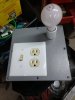
It is a working unit, (after a thorough control Deoxit) With the exception of nearly all bulbs out except the Stereo FM bulb, but will replace them all. They do have +7 volts available.
The FM section is quirky (IF selectivity) and also has oscillation in phono section only when the bass is turned up. I've seen others fix this with replacing capacitors, power board IIRC.

And recap of the tuner board. I have had good success in the past using a little Deoxit on the brass contact points in tuners as well.

Questions, even if I look at a parts list, I've gone so far as to save it. Say I decide to use Similac II for everything in electrolytic, which I have read as a good choice, I have a hard time finding small voltage in the same capacitance anywhere in stock from one supplier. I've sat down several times and started a BOM for this project.
Mouser and Digikey. I've spent several hours and still have not finished. I suppose this is from being a newbie and so many choices. And stacked film discontinued now. Is it worth the effort to source those from the big auction site?

So I see in another thread (Leestereo) 2270 rebuild, he used increased capacitance in certain areas with explanations. I need to revisit and study his post again. Thanks Leestereo.

Patfront seems to like Panasonic FC.
Good read, thanks Patfront. Thoughts?

I have also read something about changing caps on P500 Tone amp, that changes the signature sound of the unit.
Any truth to this and suggestions.

What I am saying is, I guess the smaller capacitance caps are getting harder to find in lower voltage sizes. Can I just mix brands that I can find closest in value?
I want to stay with around the same dimensions for ease of fitment. Also lead spacing, methinks better to get narrow, as they can be bent apart.

Another area I am unsure about is which caps are actually in the audio path.
And which caps are bipolar.

This is where I need the most advise.
Think I found it in the error thread,
CE23 & CE24 listed as standard 1.0 uF/50V. Use non polar caps here.

I have downloaded the schematic from HiFi Engine, for voltage readings, bias adjustments etc.
I do have a dim bulb tester, variac and good Fluke 77.
Rebuilt and modded a couple of Dynaco ST-70's. Just can't read and understand schematics. Replacing the parts, Green sheet mod, Triode EF86 driver board, bias supply, inrush current limiter, etc.
Dynakit and expansive articles make these a breeze.

Oh and last but not least, so nobody is replacing the old brown film caps in these older Marantz units, it seems?

So just take my time, do one board at a time, check my work, and recheck. Dim bulb tester after each board is completed. This should bring this 2220b back to life.

I know this post is quite sporadic, it's because I have read, attempted to make this post, added to it and read more.

Thanks in advance, I know I will probably hit snags along the way.
I know the great folks here on AK are always willing to help.

Jim
 
Register to hide this ad
I usually replace anything 4.7uF and under with WIMA film, MKS2 series 50V. The 4.7 films are kinda big, so they can pose some fitment issues. They are also non-polar, so that takes away the worry about the bipolars. But identifying the bipolar caps in the receiver is easy, just find the ones with no negative stripe. Shouldn't be very many.

Nichicon UFG are nice and widely available in values/voltages you would need. I use them frequently on tuner boards where space is an issue.

Panasonic FC are my choice for power supply board.
 
I managed to get a dim bulb tester built today. I figure I would need it after recapping the power supply, main amp and tone amp.
It passed the dim bulb test.
Then on to power it up. (Put LED lamps in too).
It comes out of protection but bias is all over the place. Started out low, and have seen it as high as 70ma. Now only around 6-10.
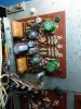
I have no output to headphones. I will have to backtrack another day to see what kind of mistake(s)I might have made.IMG_20191210_220208867.jpg IMG_20191211_161725518.jpg IMG_20191210_184711506.jpg
 
Pulled power supply board out again checking all cap size values. Board soldered traces. Thinking solder may have bridged across somewhere. Hard to tell. Rechecked replaced cap size values on main amp. Solder pads pretty straight forward on the traces there. I didn't pull the tone board. Was getting late.
The left channel bias I thought was going to settle in at 20mv. So tried setting the right channel. I got it close. Then it started dropping.
Moved back to the left still at 20. Back to right. It was at 6mv. Then back to left. It was wandering up and down but more stable than the right.
Seriously I don't know what to check next.
I should have done one board at a time.
But moved on from the Tone board because I was held up on the two bipolar caps that I failed to order.
Anybody know what I might have done?
 
Can I bump this to the top for recognition? What I keep thinking I need is the back side silk screen schematic view of the power amp board. I don't see it listed from everything I printed out off hi fi engine.
 
Last edited:
Update, all problems stem from defective, intermittent Omron relay on P700. Causes unstable bias, pops from speakers, channel drop out. I don't know how many times I had to separate the board from the output heat sink. All I knew that putting a little pressure on it changed things.
 
I took screenshots of every board and circuit from the service manual and printed them. Then I flipped the PCB images horizontally and printed them. The flipped image was incredibly helpful finding the right solder joints, and the blown up circuit boards were helpful to check my work.
 
Hi,

all problems stem from defective, intermittent Omron relay on P700.

I'm curious which 2220B relay you have. the clear one or the hazy translucent one.

This might help:
https://audiokarma.org/forums/index...eaker-relay-replacement.881545/#post-13024340

Also, "There were 2 different relays used during the production life of the 2220B. The clear covered one is comparable to a modern MY series from Omron. The hazy, translucent one doesn’t have a modern comparable."

More discussion of the issue here:
https://audiokarma.org/forums/index.php?threads/need-a-relay-for-my-2220b-not-an-my.418602/
 
Fromnowon, unfortunately I have the unobtainim hazy Type LO2-C.
I don't know what causes the actual problem it exibits. I have not pulled it from the board yet. It almost acts as bad solder joints from the terminals through the pads. But I have looked, the best my old eyes can see, even reflowed some there while replacing the caps. The magnet coil is fine, pulls the contacts down so?
I figure I will next find the thread about maybe trying to polish the contacts even though they look good.
I shall see. This thing was bought cheap enough, I thought why not try to get it going.
Sure has been a pain in the ass though.
Btw, I am quite sure this is still part of the original problem with the unit to start with.
Too much spare time started this, looked like fun at first..HA
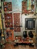
Oh, and I suspect the tuner will never work again. Gobs of white cat hair inside this thing, nice.
 
Ya, looked fun at first, heh. I've done that.

I'm not familiar with that relay, I've always been able install new, although I've had to modify things to fit.
 
Went fishing today and came back with a little different perspective on things. Of course getting away from something forgetting about it entirely sure helps.
Meanwhile back at home, back to the project something kept eating at me about that relay.
Something just didn't seem right.
Here are the bad solder joints to two pins.
Had to stop and do this post about it IMG_20191214_193605859.jpg IMG_20191214_195401226.jpg
 
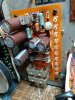
IMG_20191214_215347795.jpg Update on fixing speaker relay. This stopped all noises associated with flexing the board and wiggle test at the wire bundle leaving the power supply board, ie. picture trying to get a look at the white numbers on the rear of the board to determine J14-17. Before repairing the solder joints moving anything on the board a LOT of noises.
I assembled the board, output heat sink, output transistors, cleaned micas and transistors applied new thermal compound as if this would be final.
You get the idea.
DIM bulb test again passed.
Power on thinking bias would be adjustable this time. No, not happening. Started with trim pots (cleaned real good couple days ago) turned back close to original positions.
Voltage started out low, adjustments made.
Bias voltage still up and down. Tried this until I wanted to get a listen through speakers to check audio.
My turntable is close so decide to use this as source as FM is still not working. Still weak output, at 1/2 volume sound is distorted with pops and the oscillation noise if bass is turned up or volume increased.
Now here is the kicker, if I switch over to Aux.
with no source applied. It's almost dead quite. Even with the volume maxed.
What is the next step to get the bias to stabilize? Is it the drivers? I see Mouser has 3 listed for the replacements, all with different prefixes and 1 iirc with different gain. 200 vs 150 the other two. Would this differential pair cause the unstable bias?
What voltages should I be seeing at each pin? This would be the next step in troubleshooting correct?
 
I saved this, for my 2220B project (if I ever find time):
https://audiokarma.org/forums/index.php?threads/marantz-2220b-output-transistors.397864/

https://www.onsemi.com/pub/Collateral/2N3055A-D.PDF
"The ones that end in 15 and 16. You would need two of each."

I hope that helps! Also, I'm going to try mounting an MY2F-DC24 on stand-offs, off the board, per Catrafter suggestion back in August. I already got the relay just haven't had a chance to work on it yet. I guess I need to retire as my job seems to interfere with hobbies a lot.

I love the 2220B and the low-powered Marantz's in general. I have a 2215B also that I think is awesome.
 
Amazed my relay is ok with the known issue with them. I was afraid applying heat to fix the solder joints may do it in. Got on and off as quick as I could and still had some flow through. But it's ok.
Thanks for the link for the transistors but I believe my outputs are still good.
This machine has also been into before.
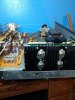
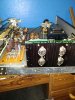
The power amplifier P700 has definitely been replaced at some point, it's a different lighter color than the rest.
The tuning capacitor P100 board looks pretty sad. It's had soldering done on it as well as quite a few of the wrapped wire posts in various other locations.
I tried to blow the schematic up large enough to print on 4 pieces of printer paper then cut edges good enough to line up and tape together.
Need to find out what is wreaking havoc on the bias voltage. Lot's of threads to go through. Tough not being and electronics tech. Although I repair motor vehicles for a living.
 
IMG_20191221_180113850.jpg IMG_20191214_215328962.jpg Unfinished posts on problems leave me in suspense wondering if they solved the problems or just gave up. So I will close this one out. I recapped every board except the tuner. Don't know exactly what stabilized the +35 volt power supply. But hung the mini grabbers on the test points and it stayed up.
Left them there shut it down for the night. Came back next day flipped the power strip on still rock solid. I was using a good known strip, from a electronics shop that had gone out of business. Reason being, these old Marantz chassis flex while standing on their ends, making their own power switch hang up, so why create a new problem. So not a mains voltage issue.
I was sure thinking something was pulling too much current from the power supply rendering R808 useless. Removed all red wires leaving J812 feeding other boards as I had read in some other PS issue posts. Still on average +28vdc fluctuating. Would hit 35 then start back down. All the while the +/- 30 volt rails never flinched. I had H805 regulator, H806 and those MUR diodes in my shopping cart. When it all became stable. Unsolved. Now I have run it two evenings straight no oscillation from the phono, speaker pops, or distortion. Did things to the tuner I knew not to touch. But now have the stations real close to the right places on the dial and even a stereo light on strong stations. Rocking R304 did not help. It was just being patient with the tuner cleaning to work, dry out and making some small trimmer adjustments on the tuner gang. It's not perfect by any means. But I can get some use out of it in the shop.
Only other thing I can think of, is when I left the mini grabbers on for a couple of days as mentioned above. At one point I had no voltage to the power amp. That's when I tapped the speaker relay. I had two separate meters set up for rechecking bias when I got the voltage back. 20mv bias and DC offset still almost perfect from previous adjustments.
I still need to replace the cut and spliced ac cord, most likely get another Omron relay ordered, wired up, faceplate, knobs cleaned up and leave well enough alone for now.
I'll take the even worse shape Pioneer SX-780 down that I put a cheap pair STK-0050's and bulbs (thanks dgwojo). Right channel lasted a week, then heard a pop. No sound. Open back up, and checked voltages. Wound up putting the stock module with numbers back in on right side.
I'll swap out the receivers and let the 2220b run just to see...
Thanks for the bulbs on this one too dgwojo.
In closing, this was a good project to get some experience. Just thought I'd share the update. Everybody likes pics on here, or it didn't happen!
 
Oh btw, C215 had been broken off previously. Got a .22 Wima there.
All tantiums got small value lyrics. I had on hand. Other things I am sure I've forgotten to mention. IMG_20191221_180808685.jpg IMG_20191221_180535665.jpg
 

Attachments

  • IMG_20191221_180425935.jpg
    IMG_20191221_180425935.jpg
    77.1 KB · Views: 10
  • IMG_20191221_180504020.jpg
    IMG_20191221_180504020.jpg
    76.7 KB · Views: 11
Last edited:
Sweet music all weekend. So final touches, cleaned faceplate, polished knobs, glued headphone jack with that fancyIMG_20191229_181557115.jpg superglue/ white-powder, installed new power cord. Wouldn't you know it, had to enlarge the hole for the bigger strain relief. Then traced L/R from the headphone jack back through the circuit PT01 - balance pot L/R. And still managed to get it reversed. Why don't they put some wire colors on the schematic..grrr.
Thought I had pics when I put that other used "upgraded" jack, no. I just ohmed gd., ring, tip. Scribed the positions, soldered and installed it without testing. (I could have looked at the one for sale on that auction site) for wiring comparison..duh. O well it was going on 10:30. Going to leave it be, I'm not going to use phones in it anyways, just put them on backwards..lol.
Main filters, change them now? Or no.
Opinions?
It seems I'd do the ring terminal trick if so.
She sure sounds good to me as is.
 
That was my thoughts as well. Will have some time new years day. What scope, probe and associated test gear do you use for the distortion measurements DDickey. My old Tek 2236 is shot.
And have never assembled any 8 ohm resistive device. I sure would like to have equipment for FM alignment. Too much to invest for this hobby
 
I got some nice non inductive 8 ohm (load) resistors at Parts Express. They are 100 watt rated if I'm remembering. A scope isn't very useful for seeing low levels of distortion, it would have to be pretty bad to see it! Perhaps a Texas based AKer with a distortion meter will see this and offer some help.
 
Back
Top Bottom