• The move to the new server is done. There are some software and database maintenance updates in process. This has us passing the hat around to help out. We appreciate any donations. Seriously, even a dollar helps. The payment page may be found here - https://www.audiokarma.org/support.html

2250 Has Developed A Smoking Habit... help.

tybrad

Lunatic Member
Banned
I was setting the dc offset v and idle currents to get them to spec. All is good.

Bulb changeout to led and new vellum layers- playing around with coloration to get from stark blue to Marantz blue-turquoise. I believe I got it.

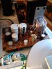
Now, the board with the relay on it has a problem. Something begins to smoke after 3 mins from a room temp start. I cannot pinpoint the component that has developed the habit. That ceramic resistor does get too hot to touch... normal?

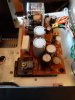
That could be it, but the smoke filament does not become visible until some distance above the board so tough to locate source Could be the 2 rect black components, could be a cap? No bulged caps. But the smoke is def from that area of upper center of board in the top image..

20220918_173331.jpg 20220918_173349.jpg 20220918_173549.jpg

The voltage across that ceramic hi-watt resistor measures out at 29.5v. Normal?

Any ideas on where to start?
 
Register to hide this ad
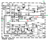
If you are referring to R807 (150 ohm), I don't think 29v drop is normal. The schematic shows one side is at 34V and the other side is probably around ~45V. So I would guess about a 10v drop across that resistor? Measure the voltage from each side of the resistor to ground.
upload_2022-9-18_15-32-19.png
 
It's likely one of the smaller resistors that is smoking and it's a symptom of a fault, not the actual fault.

I assume the protection relay is working correctly in the 3 minutes you're running it, so focus on the top half of the schematic posted by @dankik

Check for shorted diodes, zener diodes, transistor junctions.
Does the regulated voltage set correctly using R806?
 
I assume your voltage measurements are 44V on the side that goes to H808 and 20V on the side that goes to the collector of H804 (which should be 34V), a 24V diff. (Before it was 29V).
Can you check the voltage of the Zener diode H810 (WZ-140), it should be about 14V.
Also, measure the voltage at J806 to Gnd (J805). It should be 14V.
R807 is a 5W resistor and you are dissipating P = V^2 / R = (24)^2 / 150 = 3.84W.
 
Last edited:
I assume your voltage measurements are 44V on the side that goes to H808 and 20V on the side that goes to the collector of H804 (which should be 34V), a 24V diff. (Before it was 29V).
Can you check the voltage of the Zener diode H810 (WZ-140), it should be about 14V.
Also, measure the voltage at J806 to Gnd (J805). It should be 14V.
R807 is a 5W resistor and you are dissipating P = V^2 / R = (24)^2 / 150 = 3.84W.
H810- 14.1v
J806/805: 13.3v
 
It's likely one of the smaller resistors that is smoking and it's a symptom of a fault, not the actual fault.

I assume the protection relay is working correctly in the 3 minutes you're running it, so focus on the top half of the schematic posted by @dankik
Yes, the relay clicks.
Does the regulated voltage set correctly using R806?
What should that voltage be, and measured between what two points?
 
Here's what we know:
  • H810 is a 14V Zener and you measured 14.1V, so that looks good.
  • Voltage out of rectifier and into R807 looks about right.
  • Voltage drop across R807 is 24V (high), should be about 10V.
The voltage to the collector of H804 is low. Please check the following:
  • Measure resistor R807, it should be 150 ohms.
  • If you have a capacitance tester, measure C805. It should be 330uF. (You might need to unsolder one side of the cap.)
upload_2022-9-19_7-55-25.png
 
Some meters have a capacitance test function also? For now, just test resistance across R807, with power off. There's not too many components here, so we just need to narrow it down.
Sorry for asking, do you have a soldering iron and can you solder?

Might as well measure the R808 resistor, with power off. You should make two measurements with ohm meter probes one way then reversed because of the transistor in the circuit.
 
Last edited:
Yes, not new to soldering. Recapped my G9000 a while back. I am just not good on translating schematics to the board.

I am not at home right now. In a couple of hrs though.

You and @willyrover are being VERY helpful. Thank you.
 
Some meters have a capacitance test function also? For now, just test resistance across R807, with power off. There's not too many components here, so we just need to narrow it down.
Sorry for asking, do you have a soldering iron and can you solder?

Might as well measure the R808 resistor, with power off. You should make two measurements with ohm meter probes one way then reversed because of the transistor in the circuit.
R807= 150 ohms
R808= 1300 ohms, both ways.
C805= ?
Sometimes out of range, sometimes
20220919_135452.jpg
 
Hmmm... I can't tell if you multimeter can't read a 333uF cap (scale only goes to 20uF) or if the cap is bad.
Try testing using the ohms function like this:
upload_2022-9-19_15-0-19.png

The other thing to try is to verify resistance by unsolding one lead of R808 and re-measure the resistance out of circuit to see if it is 3.3k.
 
Get one of those cheap "chinese" component testers. Not super accurate, but they will tell you if you have a bad cap.

Me, after the effort of taking an old gray Elna out, I'd put a new Nichicon UPW or similar in. Waste of effort to put 40 year old electrolytic caps back in.
 
So, C805 is 330uF and measuring 4.62uF?
Seems to be. Or out of range.

Hmmm... I can't tell if you multimeter can't read a 333uF cap (scale only goes to 20uF) or if the cap is bad.
Try testing using the ohms function like this:
View attachment 2668426

The other thing to try is to verify resistance by unsolding one lead of R808 and re-measure the resistance out of circuit to see if it is 3.3k.
Did the Ohms test on the cap. With set at 2K range, jumps from low to inf very quickly- almost instantly.
If I set range to 20K, I can see the ramp up to inf resistance, So it's behaving correctly, I guess. It's just a question of its actual capacitance. I was wondering if my meter could not read to 330, but maybe? If THIS component is out of spec by that much, could it be the reason for this problem?
 
Get one of those cheap "chinese" component testers. Not super accurate, but they will tell you if you have a bad cap.

Me, after the effort of taking an old gray Elna out, I'd put a new Nichicon UPW or similar in. Waste of effort to put 40 year old electrolytic caps back in.
Right. but I still need to know if this is a failed component, causing the overall problem.
 
Like @HPMguy said since you have it out, just change it. You can change the other electrolytic, C806 also. If you pull R808 to test you can change that as well if out of spec.
 
I don't know how to test R806, I guess. It has 3 connex?

I also made an error- I measured variable R806 as 1300 and did not measure R808.
Upon closer inspection R808 is toast (and inf resistance), and has apparently been the smoker.

Now, what could cause excess current here?
 
Back
Top Bottom