• The move to the new server is done. There are some software and database maintenance updates in process. This has us passing the hat around to help out. We appreciate any donations. Seriously, even a dollar helps. The payment page may be found here - https://www.audiokarma.org/support.html

2270... first restoration questions

Preneau

New Member
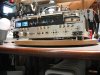
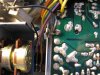
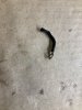
Ok... I’m starting my first restoration after purchasing a 2270 on the cheap that I expected had some issues... it does... when I opened it up I found this laying in the bottom... looks like a ground strap of some type but I cannot find where it might belong.. any help would be appreciated... I will chronicle my progress here as I go forward and follow up with more questions I’m sure...

WHEN I PURCHASED IT I KNEW SOMONE HAD BEEN IN IT PRIOR TO ME AS THE MAIN POWER SWITCH HAD BEEN REPLACED WITH A SIMPLE TOGGLE SWITCH... there was no snubber on the switch...

It powered up... no smoke or anything... all lights seem to work... hooked to speakers and no output in any mode... opened it up... found this part... now I have changed the switch with the help of another thread that had a great photo of the switch and snubber wiring...

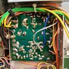
I purchased a restoration from eBay and have completed the relay board with the exception of the main chassis board ground strap... I have new strap ordered as this one looked pretty crappy...

I made one mistake that I’m questioning... when I replaced the diodes I forgot to put the sleeves from the old ones on the new ones prior to soldering... what is their purpose and do I need to remove and install them over...
 

Attachments

  • EC400604-E108-4443-843B-896CBF7EA18E.jpeg
    EC400604-E108-4443-843B-896CBF7EA18E.jpeg
    82.1 KB · Views: 74
Register to hide this ad
Heads up, eBay kits are a waste of money. Hopefully yours bothered to include a protection relay and the input pair transistors for the amp board, among other things.

Not reusing the sleeves is fine.
 
Ok... I’m starting my first restoration after purchasing a 2270 on the cheap that I expected had some issues... it does... when I opened it up I found this laying in the bottom... looks like a ground strap of some type but I cannot find where it might belong.. any help would be appreciated... I will chronicle my progress here as I go forward and follow up with more questions I’m sure...

WHEN I PURCHASED IT I KNEW SOMONE HAD BEEN IN IT PRIOR TO ME AS THE MAIN POWER SWITCH HAD BEEN REPLACED WITH A SIMPLE TOGGLE SWITCH... there was no snubber on the switch...

It powered up... no smoke or anything... all lights seem to work... hooked to speakers and no output in any mode... opened it up... found this part... now I have changed the switch with the help of another thread that had a great photo of the switch and snubber wiring...

I purchased a restoration from eBay and have completed the relay board with the exception of the main chassis board ground strap... I have new strap ordered as this one looked pretty crappy...

I made one mistake that I’m questioning... when I replaced the diodes I forgot to put the sleeves from the old ones on the new ones prior to soldering... what is their purpose and do I need to remove and install them over...

Think I remember seeing that on a corner screw holding the amp board to the heat sink on my 2252. Just holds wires to the outer edge of the board.
 
Last edited:
Does the unit look like this, with the toggle switch and flaked out tuner dial?
Marantz 2270 challenge 04.jpg
 
Think I remember seeing that on a corner screw holding the amp board to the heat sink on my 2252. Just holds wires to the outer edge of the board.

thanks...
Heads up, eBay kits are a waste of money. Hopefully yours bothered to include a protection relay and the input pair transistors for the amp board, among other things.

Not reusing the sleeves is fine.


Did get a new relay that I have replaced... haven’t opened the amp kit yet !
 
So... this is where I am... I replaced all the normal stuff on the relay protection board including the relay... when I powered it up the relay seemed to click on almost immediately... or at least chattered a bit... then off... checked 802-803 voltage and got nothing... in looking the board over I found one transistor that was not in correctly so I replaced it with one of the old ones that came out of it... still no voltage at 802-803.... I do notice that there is no wire or anything in the hole in the board at 803 ??? Suggestions ?
 
J803 is ground. You should be able to measure power supply voltage between chassis and J802. If you don’t have ~35V DC, then something is wrong in the Power supply and you will have to retrace your steps and double check all polarities, transistor orientation, and look for cold solder joints or solder bridges on the bottom of the board.
 
J803 is ground. You should be able to measure power supply voltage between chassis and J802. If you don’t have ~35V DC, then something is wrong in the Power supply and you will have to retrace your steps and double check all polarities, transistor orientation, and look for cold solder joints or solder bridges on the bottom of the board.


Ok... I will check it all over... I appreciate all your assistance...
 
There is a ground strap that goes from the bottom of the power supply board to the chassis right between the head phone jack and the volume control.
It is difficult to get the chassis lug clean and hot enough for a good solder joint.

Tom

IMG_0853.JPG
 
I have one open right now. I’ll get a couple of pics and post them. I would recommend you take some good pics of yours and post them. You will have dozens of sets of eyes to look for problems.
 
Back
Top Bottom