• The move to the new server is done. There are some software and database maintenance updates in process. This has us passing the hat around to help out. We appreciate any donations. Seriously, even a dollar helps. The payment page may be found here - https://www.audiokarma.org/support.html

2275 Phono Board P400 Left Channel Out

ZeroG

Super Member
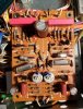
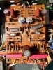
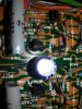
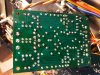
20200425_150436_resized - Copy.jpg 20200425_151956_resized - Copy.jpg 20200425_155306_resized.jpg I've been recapping a 2275 one board at a time. After recapping the phono board I found the left channel was out completely. I had replaced the 3 electrolytics, the two tantalums, and also the two 2SC248 with KSC1815.

Left channel is completely out on phono, not on FM/AM. I checked my work (again and again, as always) and everything seems to be in correctly. I matched the new small signal transistors before installation.

Of course, this is the one board I didn't test prior to recap because I didn't want to bother with unhooking my turntable, etc. Naturally this is the one with issues.

Then, I decided to check if the left channel was getting any voltage, and this is what I found:

Between J408 and J405 - 35V
Between J407 and J404 - 0V.

Should the voltages be equal at both test points? And where else do I look for the cause of the left channel being out?

Thanks in advance for assistance on this, I really appreciate it.
 
Last edited:
Register to hide this ad
Yes - that can definately be a hard time.

I'm no technician, but I think you'd better check the two replaced transistors again on the Phono-board. In the picture it looks as if you have oriented the two 2SC1815's mirrorlike. - I have just fixed an old Phonoboard on a 2245 and those boards really look alike. The two transistors are to be oriented the same way (not mirrorlike)....at least in a 2245. Please check that. (pin out aswell).

regards
Freddy
 
Recheck the orientation of replaced H405 and H406. Check the voltages at the collector of H405 and H406 both should be at 17V if both channels getting power.
 
The base of both transistors should be toward the center of the board and emitters toward the Inkedphono board after_LI.jpg outside of the board.
 
The base of both transistors should be toward the center of the board and emitters toward the View attachment 1844844 outside of the board.
I think his board is different. ECB run north and south in his photo. In his pic, the flat side of both H405 and H406 should be facing to the right. This is the same orientation as the 2230/2245/2270. You can see the ECB markings on his board and they are 90 degrees from yours.
 
I think his board is different. ECB run north and south in his photo. In his pic, the flat side of both H405 and H406 should be facing to the right. This is the same orientation as the 2230/2245/2270. You can see the ECB markings on his board and they are 90 degrees from yours.
From the pic, it looks like his board also has the bases towards the center of the board and emitter towards outside of the board. I may be wrong. just the orientation of pic is opposite of mine.
 

Attachments

  • Inkedphono board after-2.jpg
    Inkedphono board after-2.jpg
    140 KB · Views: 17
From the pic, it looks like his board also has the bases towards the center of the board and emitter towards outside of the board. I may be wrong. just the orientation of pic is opposite of mine.
Yes, yes. I misunderstood your post. Base is toward center and emitter toward bottom of pic as posted. I just remember the first one of these that I did, making the assumption that they were mirror images, and the flat surfaces both faced center. As you pointed out, they don’t. The flat faces are facing the same way — to the right in his pic.:thumbsup:
 
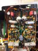
Here's a better pic of H405 and H406. The orientation does appear to be correct, right? I checked the collector voltages and at H406 it's 16.6V and at H405 it's 0.6V.

What could be causing this? What's the next step?20200425_231211_resized.jpg
 
Last edited:
They do look correctly oriented. Looks like 16.9V is the correct collector voltage. So time to work back through the odd number side of the board. There is either a bad solder joint or bad component somewhere before H405 - or H405 is bad. I’m looking at the 2325 schematic (can’t find 2275, but they have the same or similar board, I think), and collector of H401 should read 1.9V and collector of H403 should be 6.4V. Either check these with minigrabbers or a probe taped all except for the very tip to avoid accidents.
 
They do look correctly oriented. Looks like 16.9V is the correct collector voltage. So time to work back through the odd number side of the board. There is either a bad solder joint or bad component somewhere before H405 - or H405 is bad. I’m looking at the 2325 schematic (can’t find 2275, but they have the same or similar board, I think), and collector of H401 should read 1.9V and collector of H403 should be 6.4V. Either check these with minigrabbers or a probe taped all except for the very tip to avoid accidents.


Fortunately I do have mini-grabbers!

Checked the voltages:
H404 6.0V
H403 1.7V

And the last two:
H402 1.9V
H401 2.3V

I reflowed the solder on the components I replaced prior to posting. The 2275 schematic is too large a file to upload, but here's a screen grab of the P400, thanks!
 

Attachments

Last edited:
Check everything between H403 and H405, especially diodes and zeners. Maybe replace H405 in case you got a bad one.
 
Double check the wire wrap connections on J401 and J403.
Maybe something is shorting out when it's mounted. It should operate fine with the board loose.

Tom
 
I was just looking into the pic of the solder side of your board. Can you recheck the solder pad of pin J406? It looks like there is no solder. I may be wrong.
 
I was thinking about the H405. I'll do that first and report back.

H405 tests good. I replaced it anyway, since I had another. Diodes H408 (working channel) and H407 show about the same voltage in one direction. Couldn't test the C403 (4p), too small for my ESR meter. Resistors R418, R432, R426, R428 all are pretty close to spec.

H405 still shows about 0.6V.

Any ready substitutes for testing purposes for the C403 (4p) cap? I was thinking of swapping one channel for the other (with C408) if I can't get one now.

EDIT: Note revised ceramic cap numbers
 
Last edited:
Back
Top Bottom