Finally got back into my rebuild yesterday. This project is taking WAY too long but life keeps getting in the way. Unemployment has complicated my life quite a bit. I finally got a desoldering gun (Hakko FR-300) and I've been having a LOT of fun learning how to use it. I'm in the final phase of this project and I'd like to finish it this weekend but a lot depends on how things go. Again, this is my first ever rebuild and I couldn't have done it without the kind assistance of Leestereo and all of the AK'ers who have helped via PM. So, for the newbies like me, here's my next installment. This time, I'm doing the (dreaded?) PS01 board. My mistakes....errr....."learning experiences"....might help other newbies. The biggest thing I learned this time was that these thin, solid core wires are NOT happy when you move them around too much!!
PS01
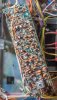
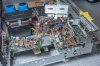
I knew that this board was going to be a bit of a hassle and Leestereo even advised me that recapping this one was "optional". But, I'm a glutton for punishment and I'm anxious to learn. Here's a view of the left side of the chassis with the amp module(s) removed. I needed to remove the Left amp mostly to make room for the upcoming recapping of the FM and AM boards. I removed the Right channel just to make the whole thing lighter. I loosened all the left side boards and the meter cluster in the hope that it would help me wiggle the PS01 board out, but that didn't help. For other newbies, the PS01 is the bottom front board and was not easily removed given all the wires attached to it. This board controls things like Dolby FM, Tape Monitors, Loudness, etc. So, I loosened it enough to get to the solder connections.
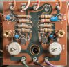
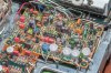
Here are the five caps used on this board along with the Mouser inventory numbers:
- CS01 - Originally 4.7uF 35v / Now 4.7uF 50v (UPS1H4R7MDD1TD
- CS02 - (same as above)
- CS03 - (same as above)
- CS04 - Originally 10uF 35v / Now 10uF 50v (UPM1H100MDD)
- CS05 - (same as above)
Not very many parts, but a pain in the butt to get to. So, to continue my practice of "work on one board, then test it", I had planned to verify my work via the headphone jack. Newbie mistake.....there is NO output on the headphone jack if the 2275 amplifier modules are not installed. Do other models have headphone amps in them?
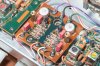
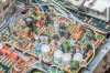
So, I got out my RCA male --> 1/8th inch female stereo adapter and plugged my headphones into the Pre-Out jacks where I heard audio....sort of. I heard a normal Right channel but the Left channel level had dropped noticeably on all Sources. I thumped and tapped all the boards that I had worked on as well as the other boards that were moved around but no changes were heard. I also discovered that my AM tuner was now dead. I quickly found the AM problem was due to my flexing the wire that attached to the bottom of the tuning capacitor. It had broken off so I resoldered it (gotta clean off that flux!!):

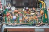
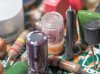
Once I fixed the broken AM wire, I went searching for the source of my weak Left channel. I found it over on the other side of the receiver! Somewhere in my tugging and pulling, I had broken off the yellow wire on the TOP of the Left channel Volume pot. The blue wire next to it was still attached to the other channel so I was praying that this broken wire was the problem. It WAS! Those two wires go from the volume pots to the Loudness switch. That broken wire was enough to drop the level of the Left channel. Here's a close-up of the yellow wire I had to replace as the original was very brittle and too short to reattach. It's seen looping around the green wire. Not a big deal, but I was SO happy I spotted it!:

I hope this helps other newbies like me. I want to get this thing finished and start enjoying it! I also did some high-res color scans of the Component Location illustrations from a clean 2275 Service Manual I purchased and will upload them with a link here.
PS01
I knew that this board was going to be a bit of a hassle and Leestereo even advised me that recapping this one was "optional". But, I'm a glutton for punishment and I'm anxious to learn. Here's a view of the left side of the chassis with the amp module(s) removed. I needed to remove the Left amp mostly to make room for the upcoming recapping of the FM and AM boards. I removed the Right channel just to make the whole thing lighter. I loosened all the left side boards and the meter cluster in the hope that it would help me wiggle the PS01 board out, but that didn't help. For other newbies, the PS01 is the bottom front board and was not easily removed given all the wires attached to it. This board controls things like Dolby FM, Tape Monitors, Loudness, etc. So, I loosened it enough to get to the solder connections.
Here are the five caps used on this board along with the Mouser inventory numbers:
- CS01 - Originally 4.7uF 35v / Now 4.7uF 50v (UPS1H4R7MDD1TD
- CS02 - (same as above)
- CS03 - (same as above)
- CS04 - Originally 10uF 35v / Now 10uF 50v (UPM1H100MDD)
- CS05 - (same as above)
Not very many parts, but a pain in the butt to get to. So, to continue my practice of "work on one board, then test it", I had planned to verify my work via the headphone jack. Newbie mistake.....there is NO output on the headphone jack if the 2275 amplifier modules are not installed. Do other models have headphone amps in them?
So, I got out my RCA male --> 1/8th inch female stereo adapter and plugged my headphones into the Pre-Out jacks where I heard audio....sort of. I heard a normal Right channel but the Left channel level had dropped noticeably on all Sources. I thumped and tapped all the boards that I had worked on as well as the other boards that were moved around but no changes were heard. I also discovered that my AM tuner was now dead. I quickly found the AM problem was due to my flexing the wire that attached to the bottom of the tuning capacitor. It had broken off so I resoldered it (gotta clean off that flux!!):
Once I fixed the broken AM wire, I went searching for the source of my weak Left channel. I found it over on the other side of the receiver! Somewhere in my tugging and pulling, I had broken off the yellow wire on the TOP of the Left channel Volume pot. The blue wire next to it was still attached to the other channel so I was praying that this broken wire was the problem. It WAS! Those two wires go from the volume pots to the Loudness switch. That broken wire was enough to drop the level of the Left channel. Here's a close-up of the yellow wire I had to replace as the original was very brittle and too short to reattach. It's seen looping around the green wire. Not a big deal, but I was SO happy I spotted it!:
I hope this helps other newbies like me. I want to get this thing finished and start enjoying it! I also did some high-res color scans of the Component Location illustrations from a clean 2275 Service Manual I purchased and will upload them with a link here.
Last edited: