

You are using an out of date browser. It may not display this or other websites correctly.
You should upgrade or use an alternative browser.
You should upgrade or use an alternative browser.
2385 reconnect PS00 to P400 pin question
- Thread starter sendust
- Start date
Register to hide this ad
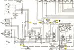
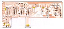

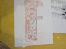
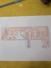
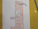
Hi Dankik, as you can see in the first photo, the board was broken and repaired by a member. I found the center new wires had came off the trace, in the second picture you can see the path i ran the new wires directly to the target pins. Can you see anything wrong, before i ran the two new wires i hade no sound left or right.
Attachments
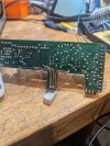
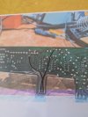
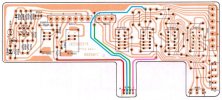
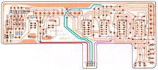
It seems to be connected properly, any idea on what would cut out the left channel, does any of the 4 coded wires affect the left channel, , could the pins be off by one notch, there are 4 pins but 6 slots? or am i barking up the wrong tree. peteHere are the traces from the connector. Each is color coded.
Your 2nd photo seems to look correct.
View attachment 3765691

Make sure that the 6 sets of cables to the correct places. Also, make sure that you do not have the connector plugged in backwards. It should be keyed or pin 1 marked with an arrow or notch. There should only be one cable with 4 conductors, the others have different amounts of wires. (See diagram below). That 4-wire cable should come from the P400 board connector J415. Unless, your tech modified it improperly from before?
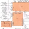
I will check all of the connectors, i was trying to confirm JS03 that connects to J415 could not be the issue with no sound on left side ,on AM FM or Phono thanks peteMake sure that the 6 sets of cables to the correct places. Also, make sure that you do not have the connector plugged in backwards. It should be keyed or pin 1 marked with an arrow or notch. There should only be one cable with 4 conductors, the others have different amounts of wires. (See diagram below). That 4-wire cable should come from the P400 board connector J415. Unless, your tech modified it improperly from before?
View attachment 3765792
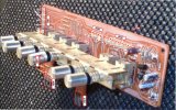
I reconnected the PS00 to the P400, I have both channels on Aux, phono. phono 2, AM. FM signal works but no sound either side. Does the PS00 have any affect on the FM sound signal or has something else happened. Also is it possible to reset frequencies, after reconnecting string something has changed and my dial is way off. Also i notice on AM setting AM light and tape light comes on, on FM setting AM FM and Tape light come on. thanks pete
Last edited:
The PS00 board does contain the FM MPX noise filter circuit and switch. All of the signals go through connector JS02. Check to make sure that you connected it correctly.
Make sure that all of the Tape Mon and Tape buttons are not pressed in.
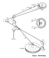
Make sure that your dial string path is correct. Also, I think there is a screw that tightens the Drum to the tuner capacitor shaft. If that is loose then the tuner capacitor will be off. Usually the dial pointer is attached to the dial cord with some glue. Is that still attached?
Make sure that all of the Tape Mon and Tape buttons are not pressed in.
Make sure that your dial string path is correct. Also, I think there is a screw that tightens the Drum to the tuner capacitor shaft. If that is loose then the tuner capacitor will be off. Usually the dial pointer is attached to the dial cord with some glue. Is that still attached?
Last edited:
The PS00 board does contain the FM MPX noise filter circuit and switch. All of the signals go through connector JS02. Check to make sure that you connected it correctly.
Make sure that all of the Tape Mon and Tape buttons are not pressed in.
View attachment 3768254
Make sure that your dial string path is correct. Also, I think there is a screw that tightens the Drum to the tuner capacitor shaft. If that is loose then the tuner capacitor will be off. Usually the dial pointer is attached to the dial cord with some glue. Is that still attached?
View attachment 3768263
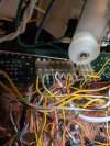
Just confirming the 7 pin connector in my photo is the one we are talking about, if so i think its right, do you know which pin on J03 or J04 would connect to the FM, if non of those i must have another issue. pete
Attachments
Last edited:
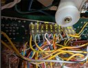
I get 0 vlt on pin 7 and 13vdc on pin 6. if i turn volume to full i can hear the station playing but just a little , does the outer metal case need to be on for proper grounding? Lastly there is a hum on both channels on fm, sounds like ground. peteYes. You should have 0v on pin 7 and 14.7v on pin 6. (UPDATED photo)
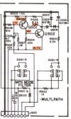
Also, check the ECB voltages on transistors QS01 and QS02
View attachment 3768492
View attachment 3768452
Last edited:
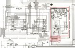
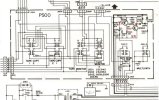
Which leg do i test, or all three on each transistor, can i use chasis for ground and just touch each pin, ?Can you please check the ECB voltages of QS01 and QS02 (dotted red box). They should be as shown above in the schematic.
View attachment 3768507
As per photoWhich leg do I test? --- Test each E=emitter, C=collector, B=base for the two transistors.
Can I use chassis for ground? --- Yes, you should be able to use the chassis for ground.
Be careful not to slip the probe and short something out.
Attachments
Your voltages on the schematic. All look OK.
Maybe QS02 is questionable because the base voltage and emitter voltage are the same. There should be a ~0.7v voltage drop due to the diode drop.
Check for a short between the emitter and base on the PC board, or shorted RS04?
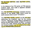
Check to make sure that the FM Muting push switch is OFF and that the MUTING LEVEL control on the back of the receiver is on minimum.
Maybe QS02 is questionable because the base voltage and emitter voltage are the same. There should be a ~0.7v voltage drop due to the diode drop.
Check for a short between the emitter and base on the PC board, or shorted RS04?
Check to make sure that the FM Muting push switch is OFF and that the MUTING LEVEL control on the back of the receiver is on minimum.
Last edited:
QS02 no short, RS04 no short but as you see in the photo there is a dead short between the pins i marked on the photo, not sure if that is connected normallyYour voltages on the schematic. All look OK.
Maybe QS02 is questionable because the base voltage and emitter voltage are the same. There should be a ~0.7v voltage drop due to the diode drop.
Check for a short between the emitter and base on the PC board, or shorted RS04?
View attachment 3768680
Check to make sure that the FM Muting push switch is OFF and that the MUTING LEVEL control on the back of the receiver is on minimum.
View attachment 3768692
Attachments
Last edited: