• The move to the new server is done. There are some software and database maintenance updates in process. This has us passing the hat around to help out. We appreciate any donations. Seriously, even a dollar helps. The payment page may be found here - https://www.audiokarma.org/support.html

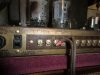
3 Grommes Precision G 101 A, 100 watt mono block tube amps

TENER, Max is pretty much right on but I will just mention that a mis-matched tube isn't really a bad tube but an amp with bad or grossly-mis matched tubes will appear as hum at the speaker. It can happen with push/pull but not so bad. Push/pull/parallel requires a little more matching skills, bias control, and tweaking.

True, hum and low frequency distortion get worse as tubes are mismatched. Distortion largely due to the core of the output transformer getting saturated by imbalanced DC current, effectively limiting its ability to do its job. Hum gets worse because the DC current though each side of the output transformer contains and equal and opposite hum signal.. which should cancel each other out unless there's gross imbalance. There's all sorts of schemes different companies have tried, individual bias controls for each tube, bias and balance controls, factory matched pairs, etc. The more anal retentive amongst us would really not sleep well without using a matched pair or quad, and then using individual bias pots to zero current the imbalance entirely.

I think though that in a more "primitive" push pull parallel amp, which was designed for industrial use, rather than to cater to audiophiles, can be effectively used and managed simply by selecting tubes properly, rather than modifying it or getting too worried.
 
This would have likely just used matched tubes originally. Note the single bias control without balance. I wouldn't be too surprised if the factory order to repair folk were to swap the whole output tube set if one went bad and just re-set the bias as needed in order to maintain reliable operation.
 
I was sent info from someone else who owns a pair. Mine just might actually be a model G 102 A instead of G 101 A. He sent me an adobie file so I don't know how to post it here. But it says that the 101 and 102 models are almost exactly the same. I can't find any more info on the 102 but the slight difference has me thinking?
 
Tener,
The bias setting for each valve needs one more step to remove early failure of the 6GT5's. The power dissipation for each valve needs to be kept below a certain level. The datasheet I was looking at has design centre max 17.5W for anode and another 3.5W for screen - but that was for horizontal deflection application. The cathode resistor voltage identifies the cathode current, so 0.9V upper limit is 45mA. The schematic indicates the anode-cathode voltage may get close to 440VDC, so 45mA x 440V = 19.8W.

Other items to note are: - there will be some voltage drop across the OPT primary winding to anode - and the cathode current includes screen current.

Operating at max design centre values was standard back then, but many now operate a bit below that to gain some extra life out of NOS tubes. As there is no design centre value for audio amp use then that adds some concern.

On balance, it seems like 0.9V bias is a max for any of the tubes, and maybe of benefit to lower that max bias setting a bit.
Thanks. do you think .8 would be good instead of .9? As long as it sounds good?
 
I'm actually curious how plate dissipation ratings for horizontal sweep duty translate to audio amp duty. If the sweep duty ratings are on the conservative side, it might be perfectly fine at 19w. I wouldn't expect it to be all that delicate a tube if four of them are making 100 watts. I also wouldn't expect the company that made it to have exceeded safe operating conditions just because of the application for such an amp. These were expected to run for long periods of time without being fooled with and you just can't do that if the tubes are being thrashed.
 
I'm actually curious how plate dissipation ratings for horizontal sweep duty translate to audio amp duty. If the sweep duty ratings are on the conservative side, it might be perfectly fine at 19w. I wouldn't expect it to be all that delicate a tube if four of them are making 100 watts. I also wouldn't expect the company that made it to have exceeded safe operating conditions just because of the application for such an amp. These were expected to run for long periods of time without being fooled with and you just can't do that if the tubes are being thrashed.

That's my thought too, the one thing an amplifier like this should be above all else, is reliable, and considering the company who made them is still in business today, I have no doubt they are reliable. Also, the tubes are still cheap, so if you need to change them in five years, it's no big deal. I wouldn't expect that to be necessary though, unless they're constantly on.

I am also curious though how sweep tube ratings compare to audio use ratings.
 
Okay I have another question. I only have 5 output taps. 2 taps for the 25v 6.25 ohm output on pins 1 and 2. 3 taps for the 70v 16 ohm output on pins 3,4 and 5. on the 70v 16 ohm output it has a center tap marked CT on #4. I was wondering if i hook up a speaker on pins 3 and 4 using the center tap would this cut the 70v 16 ohm tap in half? Would that be a 8 ohm output?
 

Attachments

  • CIMG3794.JPG
    CIMG3794.JPG
    282.8 KB · Views: 13
Okay I have another question. I only have 5 output taps. 2 taps for the 25v 6.25 ohm output on pins 1 and 2. 3 taps for the 70v 16 ohm output on pins 3,4 and 5. on the 70v 16 ohm output it has a center tap marked CT on #4. I was wondering if i hook up a speaker on pins 3 and 4 using the center tap would this cut the 70v 16 ohm tap in half? Would that be a 8 ohm output?

No, it's 4 ohms. For 8 ohms use the 6.25 ohm tap.
 
I'm pretty sure the 70v winding requires much more impedance than 16Ω. Here's the math:

For a 100watt amp to deliver full power at 70v, it must supply about 1.43 amps. (70v X 1.43a = 100watts). 1.43amp draw at 70v requires about a 49Ω load. (R=E/I or 70/1.43=49Ω). In the same way, to deliver 100watts on the 25v winding, it must supply 4amps. 4amps @ 25v requires a 6.25Ω load which does indeed match the labeling on the amp for the 25v winding.

So, you need a 6.25Ω load on the 25v winding, or a 49Ω load on the 70v. To use 1/2 of the 70v winding using the center tap, I'm pretty sure you have to limit power to 1/2 or 50watts. That is still 1.43amps @ 35v. You would need a 24.5Ω load on the 70v winding using the center tap.

Maybe there's something about the "constant voltage" distribution topology that I fail to understand, but I'm pretty sure the 6.25Ω and 49Ω loads represent the ideal load for the 25v and 70v windings, respectively.
 
Last edited:
I'm pretty sure the 70v winding requires much more impedance than 16Ω. Here's the math:

For a 100watt amp to deliver full power at 70v, it must supply about 1.43 amps. (70v X 1.43a = 100watts). 1.43amp draw at 70v requires about a 49Ω load. (R=E/I or 70/1.43=49Ω). In the same way, to deliver 100watts on the 25v winding, it must supply 4amps. 4amps @ 25v requires a 6.25Ω load which does indeed match the labeling on the amp for the 25v winding.

So, you need a 6.25Ω load on the 25v winding, or a 49Ω load on the 70v. To use 1/2 of the 70v winding using the center tap, I'm pretty sure you have to limit power to 1/2 or 50watts. That is still 1.43amps @ 35v. You would need a 24.5Ω load on the 70v winding using the center tap.

Maybe there's something about the "constant voltage" distribution topology that I fail to understand, but I'm pretty sure the 6.25Ω and 49Ω loads represent the ideal load for the 25v and 70v windings, respectively.

Yes I was tired when I wrote that. It is 50 ohm lol.
 
I'm pretty sure the 70v winding requires much more impedance than 16Ω. Here's the math:

For a 100watt amp to deliver full power at 70v, it must supply about 1.43 amps. (70v X 1.43a = 100watts). 1.43amp draw at 70v requires about a 49Ω load. (R=E/I or 70/1.43=49Ω). In the same way, to deliver 100watts on the 25v winding, it must supply 4amps. 4amps @ 25v requires a 6.25Ω load which does indeed match the labeling on the amp for the 25v winding.

So, you need a 6.25Ω load on the 25v winding, or a 49Ω load on the 70v. To use 1/2 of the 70v winding using the center tap, I'm pretty sure you have to limit power to 1/2 or 50watts. That is still 1.43amps @ 35v. You would need a 24.5Ω load on the 70v winding using the center tap.

Maybe there's something about the "constant voltage" distribution topology that I fail to understand, but I'm pretty sure the 6.25Ω and 49Ω loads represent the ideal load for the 25v and 70v windings, respectively.

Half the 50 ohm winding will match a 12.5 ohm load. The impedance ratio of a transformer is the square of the voltage ratio.
 
I see, then you're saying you can still pull the full 100 watts from half that winding and that does calculate to 12.25Ω. I was thinking that if that winding is only rated for 1.43 amps that you'd need to drop the max wattage in half to keep the current at the same max level for the winding. Thanks!
 
I see, then you're saying you can still pull the full 100 watts from half that winding and that does calculate to 12.25Ω. I was thinking that if that winding is only rated for 1.43 amps that you'd need to drop the max wattage in half to keep the current at the same max level for the winding. Thanks!

Yes, if you're using only half the secondary, it may be a good idea to limit power, however by increasing the load impedance to 25 ohms, the reflected load the tubes see will be double what it normally is. This will change the load line they operate on.
 
Tener, perhaps you should confirm how the output transformer multiple secondary windings make their way to the rear panel terminals. The aim is to have the highest percentage of output windings configured to match your speaker loading. You have previously shown secondary winding setup details - how do they relate to what is actually wired up to labelled terminals on the rear panel?
 
Back
Top Bottom