• The move to the new server is done. There are some software and database maintenance updates in process. This has us passing the hat around to help out. We appreciate any donations. Seriously, even a dollar helps. The payment page may be found here - https://www.audiokarma.org/support.html

3 Grommes Precision G 101 A, 100 watt mono block tube amps

Getting back to the difference in the transformers on mine compared to the others. The one mine has that the others don't is the output transformer and it is actually larger than the power transformer by about 1/2" in size.

Look at the radio museum version, it has a small output transformer, which looks like it wouldn't do full power anywhere near low enough. I have no idea why yours are different, but you're lucky they are, bigger is better with transformers, especially in a high power amp. And yours don't look like replacements.

You really won't know how well they work until you get the amp working and can check frequency response.
 
I used a dental mirror to look at the marks on the other transformer and I still see no numbers. Just (TP 102 A).
Look at the radio museum version, it has a small output transformer, which looks like it wouldn't do full power anywhere near low enough. I have no idea why yours are different, but you're lucky they are, bigger is better with transformers, especially in a high power amp. And yours don't look like replacements.

You really won't know how well they work until you get the amp working and can check frequency response.

Yep, I'm betting those make full power down to into the wee regions. There is certainly enough iron there.
 
Yep, I'm betting those make full power down to into the wee regions. There is certainly enough iron there.

Well that is good news. Is it common for the output transformer to be larger than the power transformer. I know these may seem like stupid questions but I have only had a few tube amps and their output transformers are smaller than the power transformer. I was just wondering if this is a odd?
 
Well that is good news. Is it common for the output transformer to be larger than the power transformer. I know these may seem like stupid questions but I have only had a few tube amps and their output transformers are smaller than the power transformer. I was just wondering if this is a odd?

For stereo amps the PT is usually larger than the OT. For mono amps sometimes smaller, same size, or larger, more dependent on Who knows why? factors such as the purchasing dept. found a blowout deal. The outputs on those are huge though. Could be they were made with shitty steel so more of it was needed but I'd bet not. The real determinant of quality is how they plot out for frequency response. They could be 30Hz - 15kHz (+/-1dB) really good, 40Hz - 10kHz (+/-3dB) not very good but can be fixed with feedback to a degree, well worse than either, or anything in-between. My gut leans towards decent considering the Grommes lineage but no definites without measurement.
 
For stereo amps the PT is usually larger than the OT. For mono amps sometimes smaller, same size, or larger, more dependent on Who knows why? factors such as the purchasing dept. found a blowout deal. The outputs on those are huge though. Could be they were made with shitty steel so more of it was needed but I'd bet not. The real determinant of quality is how they plot out for frequency response. They could be 30Hz - 15kHz (+/-1dB) really good, 40Hz - 10kHz (+/-3dB) not very good but can be fixed with feedback to a degree, well worse than either, or anything in-between. My gut leans towards decent considering the Grommes lineage but no definites without measurement.

And the good thing is, that amp uses plenty of negative feedback, and produces enough power that even if you have 50 clean watts at 35Hz, 50 Watts is still a lot of power for an amp you basically got for free. The coupling cap values don't look like they were chosen to limit bandwidth. All in all it looks like a very solid design, a variation of the classic Mullard 5-20, but with fixed bias, a different sort of input stage, and a lower impedance driver tube. The only thing which could make this amp sound bad, is if the transformers are no good. or if the 6GT5 is a bad sounding tube (I have no experience with it, but also no reasons to think it's bad) I think this design really has a lot of promise.

Another thing going for them, is a regulated screen supply.. in my experience, a regulated screen really helps a pentode based amp sound good, because the screen voltage determines gain. Even if the plate voltage varies, under load, it won't matter that much if the screen is regulated. And what a clever way to do it, by using the old ham radio inspired power supply design to get 1/2 the plate voltage for the screens, and then use tubes with a low screen voltage so only one regulator is required. This is obviously a late tube design, because it employs a very mature application of the design principals which were well known since the 50s.

 
Most commercial audio stuff was solidly built. These things were intended to be stuck in an equipment rack and run for years without any service. You just can't do that with a poorly designed piece of equipment.
 
And the good thing is, that amp uses plenty of negative feedback, and produces enough power that even if you have 50 clean watts at 35Hz, 50 Watts is still a lot of power for an amp you basically got for free. The coupling cap values don't look like they were chosen to limit bandwidth. All in all it looks like a very solid design, a variation of the classic Mullard 5-20, but with fixed bias, a different sort of input stage, and a lower impedance driver tube. The only thing which could make this amp sound bad, is if the transformers are no good. or if the 6GT5 is a bad sounding tube (I have no experience with it, but also no reasons to think it's bad) I think this design really has a lot of promise.

Another thing going for them, is a regulated screen supply.. in my experience, a regulated screen really helps a pentode based amp sound good, because the screen voltage determines gain. Even if the plate voltage varies, under load, it won't matter that much if the screen is regulated. And what a clever way to do it, by using the old ham radio inspired power supply design to get 1/2 the plate voltage for the screens, and then use tubes with a low screen voltage so only one regulator is required. This is obviously a late tube design, because it employs a very mature application of the design principals which were well known since the 50s.

Tanks maxhifi for the great info. I only have one question. You said these were a variation of the classic Mullard 5-20, but with fixed bias, I think you can adjust the bias on these. I can't remember which thread I read about it but they said it was pretty easy. Here is a pic of the bias adjuster on the amp. I hope I am right and it can be done and is not hard to do.
 

Attachments

  • CIMG3833.JPG
    CIMG3833.JPG
    74.9 KB · Views: 28
Schematic shows a bias level control, and it indicates you set it for 0.8 to 0.9 volts across the 20 ohm cathode resistors. If these were mine I might consider bringing those test points topside for easier access but thats just my 2 cents.
 
Tanks maxhifi for the great info. I only have one question. You said these were a variation of the classic Mullard 5-20, but with fixed bias, I think you can adjust the bias on these. I can't remember which thread I read about it but they said it was pretty easy. Here is a pic of the bias adjuster on the amp. I hope I am right and it can be done and is not hard to do.

I meant fixed bias as opposed to cathode bias like the mullard uses. The fixed bias on that amp is definitely adjustable, no worries. It is easy to adjust and will work fine as is.
 
Schematic shows a bias level control, and it indicates you set it for 0.8 to 0.9 volts across the 20 ohm cathode resistors. If these were mine I might consider bringing those test points topside for easier access but thats just my 2 cents.

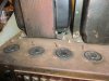
I think it was done by the factory (I wish I could find the thread that talked about it) Here is a pic of 4 insulated wires sticking up right behind each output tube. from what I read you use these to adjust bias on each tube. They said you don't need matched tubes because of this. Well I hope that is what these wires are for. Each amp has them.
 

Attachments

  • CIMG3835.JPG
    CIMG3835.JPG
    85.1 KB · Views: 44
  • CIMG3836.JPG
    CIMG3836.JPG
    88.1 KB · Views: 44
Interesting - I haven't seen that style of test point before - and using probably any available low value resistor to 'insulate' the point from chassis - still, you wouldn't want to be too forceful making a probe contact.
 
Well, it does want matched tubes because there is only one adjustment. Honestly I'm a believer in matched tubes even with individual adjustments but people disagree with me on that one.

I'd probably look at swapping those out for pin jacks if they'd fit, but thats me. My Pilot SA-260 originally used four rivets that were installed with insulating washers as test points. I ditched them for pin jacks just because it was a lot easier to plug the test leads in and adjust things rather than trying to hold the points jammed against the round rivet head with one hand and fumble around for the adjustments with my other.

Yes I agree. I was wondering how you could bias each tube with only one pot adjuster. That did not make sense to me. And the pin jack idea is great, I will have to see if they will fit but the holes do look kind of small.
 
I was wondering how you could bias each tube with only one pot adjuster.
The primary aim is to balance the sum of cathode currents on one side with the sum from the other side. That usually ends up having max and min current tubes on one side, and the max current tube needs to be managed by the bias setting to keep its nominal idle power dissipation within ratings (ie. the other 3 tubes will run cooler). The intent is that output transformer effective DC primary current is adequately low so as not to influence primary inductance and hence LF corner frequencies for stability.

Just getting idle balanced cathode currents isn't the holy grail for a hi-fi amp - that is when the mu is the same for all tubes - which nowadays can be assessed very easily by taking a PC spectrum analyser and tube switching around or rolling to get lowest harmonic and IM distortion - as the output tubes become the dominant distortion generator at moderate power levels and up.
 
the holes do look kind of small.

Drill bits fix that easily. Its more a chassis depth issue, or what might live below those resistors. Might not have the space. If not, minigrabber test leads will grab on those hooked ends easy enough.
 
If you use test leads with alligator clips on the end to measure bias, just clip one to the chassis and one to the test point. Pin jacks are a possible nice to have, but I think it's absolutely fine as is, for as often as you actually need to check bias.

As for matched tubes, I think the best you can do reasonably is buy ten 6GT5, as identical as possible made by the same company, and sort them into groups based on how they bias up. The idea is to minimize current imbalance on either side of the output transformer. Negative feedback will take care of any minor gain mismatch although ideally that would be matched too. This is an obscure enough tube though, you're not going to have a ton of selection, so I think just getting ten, sorting them into groups of four by idle current, and setting aside the two which are farthest away is kind of the way to go.
 
Drill bits fix that easily. Its more a chassis depth issue, or what might live below those resistors. Might not have the space. If not, minigrabber test leads will grab on those hooked ends easy enough.

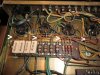
Plenty of depth under there. Just a few wires in that area that could be moved. Here is a pic arrows point at them
 

Attachments

  • CIMG3814.JPG
    CIMG3814.JPG
    373.7 KB · Views: 28
Back
Top Bottom