This issue of R or RC "sharing networks" with series diodes — both R and C are actually required for proper functioning, the R for balancing the C for diode-destroying spike suppression, but many older designs only used R — comes up enough that it is worth my time to assemble the postings I've previously made on the subject. Here they are, somewhat edited together for content. It should explain more than you care to know about series-string diodes and why most of the time it devolves into the famed meme of "UR Diode String, UR Doin' It WRONG!".
Series diodes are used because a
single diode is unavailable with a higher-voltage rating. The string works because each
individual diode in the string only sees (
V / n) where
V is the overall voltage rating for the entire string and
n is the number of diodes. (Similar tricks are used to increase the voltage ratings of resistors and capacitors.) The old books routinely suggested series diodes as a solution for higher voltage, but often failed to explain the issues, or include the sharing networks, because the author generally did not know or was repeating lore and dogma. I will explain those issues.
The attached excerpts from the
Radio Amateur's Handbook by the American Radio Relay League (ARRL) (1981) elaborate on the generally accepted electrical engineering practice for series diodes:
The Radio Amateur’s Handbook
by The Headquarters Staff of the American Radio Relay League (ARRL)
(1981)
Page 5-12:
Diodes in Series
Where the PRV rating of a single diode is not sufficient for the application, similar diodes may be used in series. (Two 500-PRV diodes in series will withstand 1000 PRV, and so on.) When this is done, a resistor and a capacitor should be placed across each diode in the string to equalize the PRV drops and to guard against transient voltage spikes, as shown in Fig. 22A. Even though the diodes are of the same type and have the same PRV rating, they may have widely different back resistances when they are cut off. The reverse voltage divides according to Ohm’s Law, and the diode with the higher back resistance will have the higher voltage developed across it. The diode may break down.
If, we put a swamping resistor across each diode, R as shown in Fig. 22A, the resultant resistance across each diode will be almost the same, and the back voltage will divide almost equally. A good rule of thumb for resistor size is this: Multiply the PRV rating of the diode by 500 ohms. For example, a 500-PRV diode should be shunted by 500 X 500, or 250,000 ohms.
The shift from forward conduction to high back resistance does not take place instantly in a silicon diode. Some diodes take longer than others to develop high back resistance. To protect the “fast” diodes in a series string until all the diodes are properly cut off, a 0.01-uF capacitor should be placed across each diode. Fig. 22A shows the complete series-diode circuit. The capacitors should be non-inductive, ceramic disk, for example, and should be well matched. Use 10-percent-tolerance capacitors if possible.
Diodes in Parallel
Diodes can be placed in parallel to increase current-handling capability. Equalizing resistors should be added as shown in Fig. 22B. Without the resistors, one diode may take most of the current. The resistors should be selected to have about a 1-volt drop at the expected peak current.
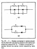
Figure 22
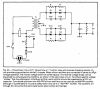
Figure 20
Pages 5-12 to 5-12:
Transient Problems
A common cause of trouble is transient voltages on the ac power line. These are short spikes, mostly, that can temporarily increase the voltage seen by the rectifier to values much higher than the normal transformer voltage. They come from distant lightning strokes, electric motors turning on and off, and so on. Transients cause unexpected, and often unexplained, loss of silicon rectifiers.
It’s always wise to suppress line transients, and it can be easily done. Fig. 21 A shows one way. Cl looks like 280,000 ohms at 60 Hz, but to a sharp transient (which has only high-frequency components), it is an effective bypass. C2 provides additional protection on the secondary side of the transformer. It should be 0.01 uF for transformer voltages of 100 or less, and 0.001 wF for high-voltage transformers.
Fig. 21B shows another transient-suppression method using selenium suppressor diodes. The diodes do not conduct unless the peak voltage becomes abnormally high. Then they clip the transient peaks. General Electric sells protective diodes under the trade name, “Thyrector.” Sarkes-Tarzian uses the descriptive name, “Klipvolt.”
Transient voltages can go as high as twice the normal line voltage before the suppressor diodes clip the peaks. Capacitors cannot give perfect suppression either. Thus, it is a good idea to use power-supply rectifiers rated at about twice the expected PRV.
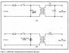
Figure 21
So, in summary, placing solid-state diodes in series without a sharing network creates serious problems which can result in device failure:
(1) Diodes in series add Vfdrop together. This doesn't matter at all for most applications. Sometimes it is even highly desirable.
(2) Diodes in series require load-balancing resistors, as above explained, or the diodes may fail.
(3) Diodes in series must have a peak rating high enough to prevent failure of an individual diode from a voltage spike above the nominal voltage rating. Once a diode fails as a short, the entire string will be overloaded and fail.
(4) Diodes in series cause the diode with the lowest Qrr to turn off prior to the others, which means that diode is hammered with the brunt of PIV blocking every cycle, which can damage or destroy that individual diode. (Remember, first diode turning off takes the full voltage at either end of the string because the other diodes are conducting, like wires.) Load-balancing resistors are thus required to avoid exceeding the steady-state voltage rating of any individual diode. That takes care of steady state. Now consider transient response, which must be similarly dealt with to avoid having one diode conduct the entirety of the voltage spike, for much the same reason. Removing the spike requires load-balancing capacitors. Suddenly series diodes becomes a lot more complex than simply using a single diode with a higher voltage rating, even if that diode is significantly more expensive.
(5) Adding more diodes increases Qrr as the sum for all diodes. This amplifies the noise broadcast throughout the amplifier (Qrr discharge spikes act like a HF carrier wave that is modulated by mains harmonics) and increases ringing by stimulating the power transformer to ring at whatever resonant frequency it has (parasitic inductance and parasitic capacitance form a tank circuit damped by its Q). Each diode needs an RC snubber to dump Qrr. This snubber was, of course, needed for a single diode but now all of the new diodes need them.
You can see (4) and (5) on a scope if you look for it. The issue of Qrr has been elsewhere been explained, and the solution of snubbers set forth in detail.
Strings of diodes thus make existing problems worse, and adds new problems which did not previously exist. The only time diode strings are appropriate is when a diode at the requisite voltage rating is not available. I always suggest purchasing (low-noise) diodes with the proper voltage rating and not adding extra diodes "just in case".
Attached is some engineering data (emphasis added):
Application Note AN443
Series Operation of Fast Rectifiers
STMicroelectronics
2004
INTRODUCTION
The use of several rectifiers connected in series is necessary to obtain voltage ratings beyond the capabilities of single diodes and also when some special requirement, such as very low switching losses, requires the implementation of several low voltage ultra fast diodes. Rectifiers connected in series tend to unequally share the voltage across the string in blocking conditions because of the variations in reverse characteristics: leakage currents and turn-off switching parameters. To ensure that each diode operates within its voltage rating, it is generally necessary to add a voltage sharing network.
...
CONCLUSION
When using several fast rectifiers in series it is necessary to make sure that no diode will be subjected to continuous or transient voltages in excess of their ratings.
In most cases, this is achieved by using sharing networks across each diode. It is important to optimize this circuit in order to reduce power consumption and to save space.



