• The move to the new server is done. There are some software and database maintenance updates in process. This has us passing the hat around to help out. We appreciate any donations. Seriously, even a dollar helps. The payment page may be found here - https://www.audiokarma.org/support.html

5000X "Unserviceable"? :(

I'm willing and able, assuming I can find the right replacement parts, I just thought these old analog tuners were persnickety and would need RF gear and an o-scope to align after replacement parts are added or they wouldn't work properly.
Persnickety... it kind of depends. When in there don't move anything around like one might on an audio board... like move a ceramic capacitor a bit for access, and definitely don't move any little coils or stubs that might look innocuous, everything was aligned with them in the position you find them.
 
Some tips:
1. check the power supply voltage at the tuner. Should be about 12V.
2. If that's ok, see if you get any sound at all in FM. Turn the muting off to check. If you get hiss, the IF section is probably ok. If it's dead silent, the problem is probably in the IF. take a piece of wire about 3 feet long and touch one end to the input of the IF board. I don't have the schematic in front of me but it will have a shielded cable connected to the tuner. You should hear something when you touch the wire to the input; hiss, static, maybe hum. If it's dead silent, the problem is in the IF and you should leave the tuner alone.
3. If you get interstation hiss on FM, the IF is good and the local oscillator in the front end is good. Go on to step 4.
4. To remove the tuning cap, turn the dial to the extreme low end, so the tuner is fully closed. Mark the plastic wheel and make a mating mark on the tuner. Rig a piece of stiff wire to hold the wheel in place after you disconnect it, so the tuning string stays in place. Loosen the set screw and move the wheel to the side. Now you can remove the tuner without having to re-string the dial cord.
5. If step 3 is true, the rf amp is probably bad. I have a source (no pun intended, tech joke) for dual gate rf fets that I will share if we get this far. Let me know what you find. Sorry I can't repair this for you, I don't ship.

 
Some tips:
1. check the power supply voltage at the tuner. Should be about 12V.
2. If that's ok, see if you get any sound at all in FM. Turn the muting off to check. If you get hiss, the IF section is probably ok. If it's dead silent, the problem is probably in the IF. take a piece of wire about 3 feet long and touch one end to the input of the IF board. I don't have the schematic in front of me but it will have a shielded cable connected to the tuner. You should hear something when you touch the wire to the input; hiss, static, maybe hum. If it's dead silent, the problem is in the IF and you should leave the tuner alone.
3. If you get interstation hiss on FM, the IF is good and the local oscillator in the front end is good. Go on to step 4.
4. To remove the tuning cap, turn the dial to the extreme low end, so the tuner is fully closed. Mark the plastic wheel and make a mating mark on the tuner. Rig a piece of stiff wire to hold the wheel in place after you disconnect it, so the tuning string stays in place. Loosen the set screw and move the wheel to the side. Now you can remove the tuner without having to re-string the dial cord.
5. If step 3 is true, the rf amp is probably bad. I have a source (no pun intended, tech joke) for dual gate rf fets that I will share if we get this far. Let me know what you find. Sorry I can't repair this for you, I don't ship.
He said the IF was working with another front end earlier in the thread......So that narrows it down some...
 
He said the IF was working with another front end earlier in the thread......So that narrows it down some...
I missed that. Good troubleshooting.
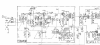
Ok, proceed to Step 4. Do not pass go, do not collect $200. Now I'm gonna take a look at the schematic. Let's all take a look at it:
upload_2018-6-26_19-36-3.png
You got 3 dual gate fets here. Oy vey. We need to eliminate at least one of them. As I said before, if you get static or interstation hiss on FM, then the local oscillator, LO, is ok. that would rule out FET03. So check and let us know. I have a way we can check FET02.
 
I missed that. Good troubleshooting.
Ok, proceed to Step 4. Do not pass go, do not collect $200. Now I'm gonna take a look at the schematic. Let's all take a look at it:
View attachment 1221351
You got 3 dual gate fets here. Oy vey. We need to eliminate at least one of them. As I said before, if you get static or interstation hiss on FM, then the local oscillator, LO, is ok. that would rule out FET03. So check and let us know. I have a way we can check FET02.

I'm definitely getting static, and when I probe the input to the IF board with a wire as suggested, the static gets louder. So presumably this narrows us, at least on a preliminary basis, past FET03? I'm looking for a place to probe the front end circuit to make sure it's getting power. Will update.
 
Last edited:
On a side note, that schematic shows several instances of what looks like a wire actually passing through the dielectric of a 1000uf capacitor (or is it 1000pf? units are hard...). Obviously that's not what's actually happening... is this an older convention implying that at that point in the circuit you're attaching a cap to ground (presumably to isolate that line from noise...)?
 
Last edited:
On a side note, that schematic shows several instances of what looks like a wire actually passing through the dielectric of a 1000uf capacitor (or is it 1000pf? units are hard...). Obviously that's not what's actually happening... is this an older convention implying that at that point in the circuit you're attaching a cap to ground (presumably to isolate that line from noise...)?

Without ever having seen the ones in use here, they sound like what I would call 'feed through capacitors'. (1000 would be 'pF') And yes, they are used to filter off noise/RF from the line passing through - the style of construction of these means that the grounded side has zero lead length = zero inductance = maximum capacitive filtering effect.
 
Without ever having seen the ones in use here, they sound like what I would call 'feed through capacitors'. (1000 would be 'pF') And yes, they are used to filter off noise/RF from the line passing through - the style of construction of these means that the grounded side has zero lead length = zero inductance = maximum capacitive filtering effect.
They should be located on the chassis of the tuner.
 
I missed that. Good troubleshooting.
Ok, proceed to Step 4. Do not pass go, do not collect $200. Now I'm gonna take a look at the schematic. Let's all take a look at it:
View attachment 1221351
You got 3 dual gate fets here. Oy vey. We need to eliminate at least one of them. As I said before, if you get static or interstation hiss on FM, then the local oscillator, LO, is ok. that would rule out FET03. So check and let us know. I have a way we can check FET02.

Maybe I am looking at this wrong, but it looks to me like FET 101 and FET 102 are RF preamplifiers, TR 101 is the local oscillator, and FET 103 is the mixer. In the schematic for the 5000A (as opposed to the 5000X), the FETs are shown as Motorola part MFE3007, maybe this would make a decent sub for the Japanese parts used in the 5000X if one is easier to find than another. I found that the MFE3007 is reasonably easy to find online.
 
Last edited:
Without ever having seen the ones in use here, they sound like what I would call 'feed through capacitors'. (1000 would be 'pF') And yes, they are used to filter off noise/RF from the line passing through - the style of construction of these means that the grounded side has zero lead length = zero inductance = maximum capacitive filtering effect.

Awesome. Thanks for the education.

I ran out of time last night, but probing some of the FET leads gave voltages around 4V DC on a couple of them. Unfortunately, it was an abortive attempt and it's probable i'm going to have to take the bottom panel off to make sure i'm seeing 12V incoming to the front end (near what's marked as (M) in the schematic, which is actually a line in from the 14V source through the Source Select knob and stepped down through a 47 ohm resistor)... I'm not sure the 4V is reflective of the power being adequately applied to the front end or if it's instead bleeding through from other adjacent circuits like the IF board.

So, i'm guessing from what has been said here that I wouldn't get hiss when listening if the IF board or the oscillator were messed up (which fits with my findings from eternity ago)... is there a way to narrow to one of the three FETs, or should I just bite the bullet and replace them all? The circuits in there are very tight and I can see why the service shop might have thrown up their hands at it, but I'll see if I can give it a go on the recommendation of you guys before I consider buying a replacement front end.
 
Maybe I am looking at this wrong, but it looks to me like FET 101 and FET 102 are RF preamplifiers, TR 101 is the local oscillator, and FET 103 is the mixer. In the schematic for the 5000A (as opposed to the 5000X), the FETs are shown as Motorola part MFE3007, maybe this would make a decent sub for the Japanese parts used in the 5000X if one is easier to find than another. I found that the MFE3007 is reasonably easy to find online.
Oops, you are correct:
Fet 101 and 102 are the rf amps (also 102 is only single gate) Fet 103 is the mixer and TR101 is the LO. So likely the LO is good, Connecting a 6 foot wire to the gate of Fet 103 you may get some weak reception or at least you will get more static. If not, Fet 103 is bad. If you get reception or noise at Fet 103 go to the gate of Fet 102, it should then have more gain. If not, Fet 102 is probably bad. If you get gain at Fet 102 go to the gate of Fet 101. I am talking about the top gates here.
 
So here's an interesting finding... the supply to the front end is indeed measuring 4V DC (6V prior to the 47ohm resistor, stepped down to 4V where it enters the tuner). Is that expected-- I got the impression it should be more like 12V? Based on my reading of the schematic, the tuner is sourced by (M), which is a tap off of what looks like a 14V supply when the Selector is set to FM or FM AUTO.

EDIT: that supply is at 14V when switched to AM, which is where the schematic shows it at, so maybe it's supposed to be 6V on FM. Can't tell from the schematic. Will try the 6ft wire technique from dr*audio.
 
Last edited:
Just tried 6ft wire technique attached to top gate of FET03. Background hiss stays steady, crackling is louder, perhaps a low frequency hum added. Would hitting it with freeze spray tell me anything, or just contaminate the circuitry?

Moved on to FET02 and FET01, nothing changed about the signal when attaching 6ft wire to either.
 
Last edited:
The supply should stay at or close to 14V, something in the tuner is drawing excess current. Try and remove C020 and check if it's shorted out and the voltage recovers.
 
C020 is a good suggestion-- ancient electrolytic that it is. I probably won't have time to desolder-solder until this weekend, but I'll give it a go.
 
C020 is a good suggestion-- ancient electrolytic that it is. I probably won't have time to desolder-solder until this weekend, but I'll give it a go.

I think chances are its not causing the problem, but it's a heck of a lot easier to check than it is to change one of those FETs, so probably best to check the easy to deal wirh stuff first.
 
I think chances are its not causing the problem, but it's a heck of a lot easier to check than it is to change one of those FETs, so probably best to check the easy to deal wirh stuff first.

I'm sure I wouldn't get that lucky, certainly. But it might make the rest easier to diagnose.
 
Back
Top Bottom