• The move to the new server is done. There are some software and database maintenance updates in process. This has us passing the hat around to help out. We appreciate any donations. Seriously, even a dollar helps. The payment page may be found here - https://www.audiokarma.org/support.html

6336A...

knockbill

Lunatic Member
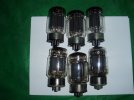
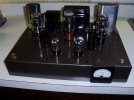
I picked up 6 of these on Friday at K'town,,, they seem to be related to 6080/6AS7,,, but are 30W... output, but 5A heaters! I built a 6AS7 amp a while ago,,, and it sounds pretty good,,,
Here's a data sheet I found for them,, cool looking KT type bottles...
6336A datasheet — pinout & specs | Amperatubes
My buddy had them in his tubes for a buck box,, so I grabbed em,,, I found an AK discussion about them from 2003 IIRC,,, Anyone ever try to build an amp with them recently? Looks like they need a stout PT,,, and I have a bunch of them,,, Just gotta look for a schematic,,,
 

Attachments

  • P1010006.JPG
    P1010006.JPG
    90 KB · Views: 27
  • P6090008.JPG
    P6090008.JPG
    87.9 KB · Views: 27
Register to hide this ad
5 amp.l heaters?, wow! I have a 10 amp 6V center tapped filiment transformer and its pretty good sized. It would only be able light up two of those.
 
Hey Paul,,,
I doubt it would light up two of them,, as I used (actually tried) a NOS Triad 10A FT for my 811 build(4A heaters) and it got really hot! Luckily I had two FTs and thats how its built!!!
 
Last edited:
I did a little research on DIYaudio and AK,, and it looks like Kegger(RIP) built an amp with these tubes,,, I saw pics of teh amp,, haven't found his schem yet tho...
 
Someone here on AK, I forgot who though has a lot of Kegger's documents.
Hopefully someone can help with that. It sounds like a fun project.
 
per the datasheet each triode is roughly a parallel 6080, its a heck of a tube. Very low gain but high current handling. The plates on those things are serious heavy duty too, thick graphite sections. Should be able to run moderate voltage but a lot of current into a fairly low impedance transformer and get good power. Needs a heck of a power transformer to supply that sort of B+ current though.
 
per the datasheet each triode is roughly a parallel 6080, its a heck of a tube. Very low gain but high current handling. The plates on those things are serious heavy duty too, thick graphite sections. Should be able to run moderate voltage but a lot of current into a fairly low impedance transformer and get good power. Needs a heck of a power transformer to supply that sort of B+ current though.
Yep,,, like I was saying,,, I have some massively serious PTs,,, in the say 5-6" square potted type,,, I'm sure I have iron for it, but doubt I'll be able to move it off teh bench when its done!!! Maybe try one channel if I find a schematic that makes sense, and go from there... Just thought for a winter project...
Mike has more of these tubes left in teh box,,, guess I was the only one dumb enough to take any!!!
 
Yeah -- The heater alone dissipates 30+ watts -- way more than a 7591 can dissipate from its heater, plate, and screen combined run at absolute maxed out ratings.......

Dave
 
Good grief, that thing is a monster, and you have SIX?!?!

Would be fun to do an all-dual-triode single-ended stereo amp, make nerds like us wonder how you're getting stereo out of one old KT88.
 
Yeah -- The heater alone dissipates 30+ watts -- way more than a 7591 can dissipate from its heater, plate, and screen combined run at absolute maxed out ratings.......

Dave
Yep,,,
I seem to find a lot of weird tubes that no one wants at hamfests and antique radio shows,,, I'll try to build a test channel with one of these for a winter project,,, if I can find a schematic,,, This thing could be come the new shop heater, if it works out!!1
 
Those 6336s are some really beefy tubes- but have some rather odd operating anomalies.

One of which, is the imbalance between tube sections. As these were not intended tor audio- there was no consideration given to balancing sections. One of the things this leads to, is biasing problems, if one ever tries to use the two sections in parallel. The only way that can work, is to cathode-bias (with a bypass cathode cap) EACH cathode INDIVIDUALLY. Apparently, it is possible to connect plates in parallel, as long as the cathodes are on separate cathode bias resistors.

Secondly, is the need for INDIVIDUAL grid stoppers. 1K grid stoppers are recommended- but one must use SEPARATE grid stopper resistors on EACH grid, even if the tube is used in parallel.

Thirdly- low-value grid bias/ground resistors are paramount. Some data sheets say that 200K per grid bias resistor is OK- but, realistically, 100K is probably a much safer value.

Fourthly- these tubes, due to very high Miller capacitance and very low gain, need "god's own driver circuit". Both high current AND high voltage. It can take close to 100V AC signal drive voltage, at pretty high current levels, to not wind up with HF anomalies. This is a case, where maybe something with very low plate impedance, like a triode-strapped EL84 as a driver, per side or something like a paralleled 6SN7, per side, could be applicable. You will need probably close to 400V, or so, preferably 450V, for the B+ supply for the driver tube.

Fifth- the 6336 needs to be warmed up (heaters on) for probably 20 to 30 seconds or so, before B+ is applied. Not doing this can damage the tube, causing noise, runaways, and other problems!

OTOH- One distinct ADVANTAGE of using 6336s as output tubes, is that they, themselves have ASTRONOMICALLY LOW plate impedance. This means they can usually drive some transformers, that would badly misbehave on other higher-plate-impedance output transformers. Response anomalies on either end of the spectrum may well be reduced, for output transformers. And, with 30 watts dissipation per plate- a pair of these in a push pull circuit (essentially parallel push pull) should be able to put out the power of parallel push pull 300Bs, on similar output transformers- potentially up to 50-70w per channel. And they may actually have better bass, due to the even lower plate impedance.

Regards,
Gordon.

 
Hi Gordon,
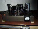
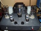
Thanks for your reply,,, Well, I'm sure you are correct,,, I built the 6AS7 amp (pic in post #7),,,, There's a selector switch with separate bias/balancing pots for each triode, set at approx 90V IIRC... Theres pair of Pioneer OPTs under the chassis.. It does have good Bass...
 
6BX7 or 6BL7 might be a better choice than parallel 6SN7, though at the expense of lower gain. Keeping with the octal theme though, triode-wired 6K6 or 6V6 would also get it done. Given the physical size of a 6336A I think a 9 pin tube would look a bit "off" sitting in front of it.

Given the imbalance issues I'd probably want to use these as one plate per-side in a push-pull rig rather than parallel plates. I'm personally not a massive fan of parallel tubes anyway, mismatches between tubes or sections just seem likely to cause too many issues. I might do something like a partially-shared cathode resistor with a balance pot to even out the current draw. Think like what some of the Williamson amps did.

SE is also an option of course, one tube per-channel, individual bias parts and whatever else.
 
Another option would be to use a CCS on each cathode to generate equal bias currents and then either cap bypass the CCS's or couple the cathodes with a capacitor to form a differential output stage. I've done the differential version in a driver stage and have seen an article about doing this with the 6AS7 in an output stage. The cathode coupled class A version gives less power but might sound really good.
 
6BX7 or 6BL7 might be a better choice than parallel 6SN7, though at the expense of lower gain. Keeping with the octal theme though, triode-wired 6K6 or 6V6 would also get it done. Given the physical size of a 6336A I think a 9 pin tube would look a bit "off" sitting in front of it.

Given the imbalance issues I'd probably want to use these as one plate per-side in a push-pull rig rather than parallel plates. I'm personally not a massive fan of parallel tubes anyway, mismatches between tubes or sections just seem likely to cause too many issues. I might do something like a partially-shared cathode resistor with a balance pot to even out the current draw. Think like what some of the Williamson amps did.

SE is also an option of course, one tube per-channel, individual bias parts and whatever else.
Exactly... that's how the 6AS7 amp is built,,, PP in one tube with the balance pot/ckt you helped me design,,, Most any 6AS7 I put in it will balance with the range of the pot/ckt... I was never considering paralleling the two triodes in one bottle,,, I think the schem for how the 6AS7 amp is biased is on here someplace, if it didn't get lost in an update...
 
Those 6336s are some really beefy tubes- but have some rather odd operating anomalies.

One of which, is the imbalance between tube sections. As these were not intended tor audio- there was no consideration given to balancing sections. One of the things this leads to, is biasing problems, if one ever tries to use the two sections in parallel. The only way that can work, is to cathode-bias (with a bypass cathode cap) EACH cathode INDIVIDUALLY. Apparently, it is possible to connect plates in parallel, as long as the cathodes are on separate cathode bias resistors.

Secondly, is the need for INDIVIDUAL grid stoppers. 1K grid stoppers are recommended- but one must use SEPARATE grid stopper resistors on EACH grid, even if the tube is used in parallel.

Thirdly- low-value grid bias/ground resistors are paramount. Some data sheets say that 200K per grid bias resistor is OK- but, realistically, 100K is probably a much safer value.

Fourthly- these tubes, due to very high Miller capacitance and very low gain, need "god's own driver circuit". Both high current AND high voltage. It can take close to 100V AC signal drive voltage, at pretty high current levels, to not wind up with HF anomalies. This is a case, where maybe something with very low plate impedance, like a triode-strapped EL84 as a driver, per side or something like a paralleled 6SN7, per side, could be applicable. You will need probably close to 400V, or so, preferably 450V, for the B+ supply for the driver tube.

Fifth- the 6336 needs to be warmed up (heaters on) for probably 20 to 30 seconds or so, before B+ is applied. Not doing this can damage the tube, causing noise, runaways, and other problems!

OTOH- One distinct ADVANTAGE of using 6336s as output tubes, is that they, themselves have ASTRONOMICALLY LOW plate impedance. This means they can usually drive some transformers, that would badly misbehave on other higher-plate-impedance output transformers. Response anomalies on either end of the spectrum may well be reduced, for output transformers. And, with 30 watts dissipation per plate- a pair of these in a push pull circuit (essentially parallel push pull) should be able to put out the power of parallel push pull 300Bs, on similar output transformers- potentially up to 50-70w per channel. And they may actually have better bass, due to the even lower plate impedance.

Regards,
Gordon.
Since the sections aren't going to be matched, and instead of having to have fixed bias for each section, what about having one section catbode biased and the other with fixed bias? Then you would only have to adjust the one section to match the cathode biased section. It would be half the bias adjustments needed. I dunno if this would be workable, it's just something that popped into my head if someone were to try and build a PPP amp with these tubes.
 
Guess that would depend which section was adjustable,,, With one pot, you really dont have choice which triode you can adjust as it will depend how how the tube is balanced... I never won a 50-50 chance!!!!
 
Back
Top Bottom