• The move to the new server is done. There are some software and database maintenance updates in process. This has us passing the hat around to help out. We appreciate any donations. Seriously, even a dollar helps. The payment page may be found here - https://www.audiokarma.org/support.html

6SL7/6BL7 driven Electra-Print 300B

maynard999

New Member
I have a thread on another forum about this project, but I might be missing some folks that hang out here. I'm looking for last minute feedback from folks smarter than me (plenty of you out there). I found an Electra-Print 300B schematic that caught my eye a while back and I was ready to take on a 300B project. I have a lot of 6BL7 tubes around from another project. I know they're out of production, but that doesn't worry me. I have plenty and great NOS are cheap on Ebay. Also, 6BX7 can be used as a substitute and I have just as many of those.

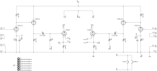
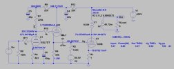
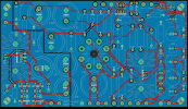
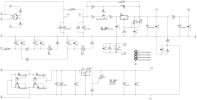
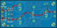
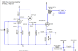
I've attached the original schematic that insprired this project, filament PS board jpg and schematic, power supply board jpg and schematic, and the driver jpg and schematic. A SPICE simulation from EURO21 is also in here. Things are staying true to the original design with a few minor changes including dialing the B+ down to 400V. The last picture is the $2k worth of Monolith Magnetics that showed up last week.

The project is moving along. I'm going full PCB with this and not skimping on components. That consists of a Monolith custom power supply, 10H choke, SA-9 output transformers, and high end components throughout. I'm getting ready to send my Gerbers to have boards made and put in a huge Mouser order. Chassis will follow after successful bench testing. Please look at my attachments and provide feedback. A few open questions are:

  1. Any downside from the last RC filter in the power supply that feeds the driver tubes? Anode AC shunted to ground was a previous comment when I had separate RC filters before the 6BL7 and the 6SL7. It's easy enough to jumper R18 and leave C19 and C20 unpopulated and stay true to the original design. Seems like there could be an advantage with the RC to decouple from the B+ going to the 300Bs.
  2. Pros/cons of using different value attenuators (50k, 100k etc)? The original design has a 40k resistor on the input.
  3. Ground or float the filament power supply? I've read both being done as well as a small value resistor to ground.
Thanks in advance
 

Attachments

  • 300B Driver Schematic.png
    300B Driver Schematic.png
    52.3 KB · Views: 41
  • 6SL7, 6BL7, fix bias 300B 3k3 SE SPICE at 400V.jpg
    6SL7, 6BL7, fix bias 300B 3k3 SE SPICE at 400V.jpg
    44.2 KB · Views: 46
  • 300B_SE_6SL7_6BL7_3K.gif
    300B_SE_6SL7_6BL7_3K.gif
    13.1 KB · Views: 49
  • IMG_3001.jpg
    IMG_3001.jpg
    113.1 KB · Views: 42
  • 300B Power Supply.png
    300B Power Supply.png
    440 KB · Views: 32
  • 300B Power Supply Schematic.png
    300B Power Supply Schematic.png
    67.5 KB · Views: 26
  • 300B Filament Power Supply Schematic.png
    300B Filament Power Supply Schematic.png
    31.5 KB · Views: 26
  • 300B Filament Power Supply.png
    300B Filament Power Supply.png
    291.2 KB · Views: 23
  • 300B Driver.png
    300B Driver.png
    150.1 KB · Views: 34
Last edited:
Register to hide this ad
I'll admit to being less than enthusiastic about most schematics I've seen from Electra-Print. In this case, I have to ask a question - what's the purpose of using a 6BL7 follower to drive the 300B? A cascade 6SN7 should handle this pretty well and not invite the Miller effect of the 6SL7. Where is the other forum where this is under discussion?

Jack
 
To answer some of your questions...

1. The B+2 directly after the 317 being decoupled by a 200 Ohm resistor in not much decoupling. I'd just use a B+ and decouple from there with more standard value components/design.
2. Input attenuator values depend on what will be driving the amp. 50~100k seems to be a good compromise if you use both tube & SS preamps.
3. With fixed bias, you can ground the negative filament node and be good. Try floating or grounded and see if there is any performance advantage.

A 6EA7/6EM7 tube is similar to what you have posted and has less demanding filament power. You could use 1 tube per channel without sharing triodes for left/right.
 

Attachments

  • 6EA7 Example.png
    6EA7 Example.png
    91 KB · Views: 13
The EP 6sl7/6bl7 circuit was the first one I tried in my 300B amps. I used it for a month or two before going on to try over a dozen other driver circuits. I never went back to the EP, but my recollection is it sounded quite nice, just not the best. My favorite was a 6sl7 cap coupled to a choke-loaded 6em7 (low gain section). The high-gain section of the 6em7 is very similar to a 6sl7 so it might seem reasonable to use just the 6em7; however I recommend using a separate 6sl7 instead because that allows you to choose the best sounding tube for each section. There are many varieties of 6sl7 tubes but not so many 6em7 tubes.
 
The EP 6sl7/6bl7 circuit was the first one I tried in my 300B amps. I used it for a month or two before going on to try over a dozen other driver circuits. I never went back to the EP, but my recollection is it sounded quite nice, just not the best. My favorite was a 6sl7 cap coupled to a choke-loaded 6em7 (low gain section). The high-gain section of the 6em7 is very similar to a 6sl7 so it might seem reasonable to use just the 6em7; however I recommend using a separate 6sl7 instead because that allows you to choose the best sounding tube for each section. There are many varieties of 6sl7 tubes but not so many 6em7 tubes.
Can you share the 6EM7 schematic?
 
I get that point-to-point is more classic tube amp. Two different means to the same end, each having advantages.
There are no advantages to the PCB other than its better physical adaptation to small solid state components and mass production labor savings. It carries the distinct disadvantage of restricting tweaks and component swaps, the need for which often become more apparent after the unit is built and tested and burned in. I design PCBs for solid state control circuitry and voltage regulation. However, chassis-mounted tube sockets and point-to-point wiring are much more appropriate for the signal path in one-off production of vacuum tube circuitry.

Jack
 
Last edited:
There are no advantages to the PCB other than its better physical adaptation to small solid state components and mass production labor savings. It carries the distinct disadvantage of restricting tweaks and component swaps, the need for which often become more apparent after the unit is built and tested and burned in. I design PCBs for solid state control circuitry and voltage regulation. However, chassis-mounted tube sockets and point-to-point wiring are much more appropriate for the signal path in one-off production.

Jack
I'm guessing there are other threads devoted to the topic of PCB vs point-to-point. Let's pretend mine is point-to-point. Do you have any input on the design that might help me optimize it? Appreciate your help.
 
I'm guessing there are other threads devoted to the topic of PCB vs point-to-point. Let's pretend mine is point-to-point. Do you have any input on the design that might help me optimize it? Appreciate your help.
I've already given you one idea. You never answered my question though. I'd like to see previous discussions before spending time going into more detail.

Jack
 
I've already given you one idea. You never answered my question though. I'd like to see previous discussions before spending time going into more detail.

Jack
There is a thread of the same title on DiyAudio. I'm not an electrical engineer and I'm still learning from each of my tube projects. This is a borrowed design from Jack Elliano and I can't really speak to his particular choices for this circuit. I was just interested in trying something a little different that might take advantage of some odd tubes I have around.
 
There is a thread of the same title on DiyAudio. I'm not an electrical engineer and I'm still learning from each of my tube projects. This is a borrowed design from Jack Elliano and I can't really speak to his particular choices for this circuit. I was just interested in trying something a little different that might take advantage of some odd tubes I have around.
The 6BL7 and 6BX7 are terrific tubes for certain purposes. I use a paralleled 6BL7 as a cathode follower to drive the 211 in my SETs. However, unlike the EP design, they're direct coupled, so the high standing current of the 6BL7 allows smooth operation into A2 operation (grid current). That can't happen in the EP design due to the coupling cap, so most of the useful characteristics of this tube are wasted. I really think there are better ways to drive a "no-feedback" 300B than to start with a 6SL7.

I'll take a look over at DiyAudio when time permits.

Jack
 
I can but I will have to wait until I return home in a few days. I have it in my files at home but I am on vacation right now.
I might be out of luck with heater current to consider it an option. Budgeted for 1.8A of DC with 3.6A coming off the PS transformer with my 6.3V winding.
 
I get that point-to-point is more classic tube amp. Two different means to the same end, each having advantages.
Sadly they don't come to the same end. PC board tube amps are much more likely to end up with hum, oscillations and other issues as the signal path is routed so close to other things like heaters etc. Also power tubes shed off a lot of their heat through the tube pins, which over time end up cooking the PC board. I honestly can't think of an advantage for using a PC board other than cost savings in a commercial mass produced amp.
 
Sadly they don't come to the same end. PC board tube amps are much more likely to end up with hum, oscillations and other issues as the signal path is routed so close to other things like heaters etc. Also power tubes shed off a lot of their heat through the tube pins, which over time end up cooking the PC board. I honestly can't think of an advantage for using a PC board other than cost savings in a commercial mass produced amp.

Well, I have to disagree with some of that. I love my Williamson PCBs. They're dead quiet, they measure beautifully, there's little to no chance of broken resistor leads or other issues in shipping, little chance of cold solder joints, and any failures are easy to spot and repair. The Belton PCB octal sockets are mounted on stand-offs to reduce strain on the board, with extended pins to minimize heat transfer. In addition, it's easy to make any number of modifications on the fly. Granted, the filament wiring is added by hand since it's AC, but otherwise they make for a tidy, solid, reliable and consistent build. I've also used some PCBs for my Aikido preamps and they are are also not at all problematic, with DC filaments of course.

OTOH, the Tubes4HiFi SP14 board is rather notorious for being susceptible to ground loops. I think it just depends on the quality of the board and the design.
 
My general opposition to PCB with tubes is the heat damage, but modern ones are far less prone to that. Not going to tell you I love looking at them but under-chassis mount so its hidden is fine.

design problems are not really specific to the construction method. Its highly possible to have ground loops or other issues with point to point wiring too.
 
I really didn’t intend for this thread to become a debate about PCB vs point-to-point. I bet that thread does already exist.

I do appreciate any advice regarding this design so I can take the next steps.
 
Back
Top Bottom