• The move to the new server is done. There are some software and database maintenance updates in process. This has us passing the hat around to help out. We appreciate any donations. Seriously, even a dollar helps. The payment page may be found here - https://www.audiokarma.org/support.html

6SN7 LTP and CSS Question

LinuxGuru

Well-Known Member
Hi,

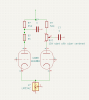
Is it possible to use 10M45S as cathode current source in 6SN7 LTP shown on schematic? From simulation it appears that cathode bias voltage is only about 10V and I don't know for sure if this is enough for depleted mode mosfet.
Another option is a 10mA constant current (limiting current) diode like LM334Z (40V/400mW max, which seems enough). Currently have no data how LM334Z (which was designed for power supplies) will behave in audio circuits.

Thanks in advance for any suggestion(s).Screenshot at 2022-10-01 16-27-11.png
 
Register to hide this ad
My main hi-fi amp, in fact, uses a 10M45S in the tail of the 6SN7 long-tail pair phase PI/driver section. However, it's not 10V being dropped across... more like 130V. The overall topology is a modified Mullard 5-20 style... 12AX7 triode gain stage DC-coupled to 6SN7 long-tail pair with a constant current sink in the tail, AC-coupled to 6L6GC power stage. The B+ rail for the 6SN7s is 400V, and I drop about 1/3 of the voltage across each part of the LTP (plate load resistors, triode, CCS tail). Approximate voltages on the 6NS7: plate 279V, grid 125V, cathode 130V. Current through the 10M45S is 9ma. The prior stage is a pretty run-of-the-mill 12AX7 gain stage: 200V B+ rail, 100K plate load, 125V plate voltage, 1V cathode voltage.

I can't tell for sure here because the schematic is cut off, but it looks to me like you're AC-coupling the gain stage to the LTP?
 
VTA uses the LM334 in a low voltage scenario such as yours. Their schematic shows about ~10V on the cathodes of the 12AU7 LTP.
 
I can't tell for sure here because the schematic is cut off, but it looks to me like you're AC-coupling the gain stage to the LTP?

It is C-coupled. Design of first stage not finished yet, I'm thinking about CSS as plate load of 12AX7.
Thanks for clarification about 10M45S, I didn't expected that CSS will eat 130V.
 
1k would not be enough of a tail resistor I don't think. Might be about right for a standard voltage amp with a shared cathode but the voltage swing across it probably wont be enough for grounded grid operating.
 
Interesting thread for me, I have a stage in my 6L6GC balanced amp that's almost exactly the same as this. 6SN7 driver with both grids fed and I want to try turning it into an LTP with a CCS at the cathode to see what the performance impacts are. I'm gonna throw a LM334Z in my next order for fun. It's so cheap and worst case scenario it dies, but sounds like a fun experiment.
 
If you do this, it will not be possible to adjust the LTP to cancel imbalance in the output stage. Just sayin'...

Jack
 
It's a pot in the LTP plate circuits that let's you adjust the load between each half to compensate for overall imbalance in the push-pull outputs and OPT. Output tubes and transformers can have an imbalanced transfer so this let's you "imbalance" the the gains between the halves of the LTP to offset the other imbalances. Ideally you need to be able to measure THD to make the adjustment. I think Fisher included this sort of adjustment in many of their amp circuits in the concertina phase splitters they used. HK did this in the LTP section of the Citation V and called it AC balance.
 
Ah, in the plate circuit, that makes sense. Could one use a CCS and adjust the gain at the input of each grid to achieve the same effect?
 
It is C-coupled. Design of first stage not finished yet, I'm thinking about CSS as plate load of 12AX7.
Thanks for clarification about 10M45S, I didn't expected that CSS will eat 130V.

CCS plate load of the 12AX7 stage would work fine. I've used that before in a pre-amp (that I've prototyped and made the PCBs for, but still haven't finished building because I have too many projects, lol).

I would enthusiastically recommend you consider DC-coupling the first stage to the LTP. It will let you run the LTP in the sweet spot (following the "rule of thirds" I mentioned earlier). Otherwise, you might want to consider "lengthening" the tail by tying the cathode circuit to a negative rail rather than to ground.
 
Ah, in the plate circuit, that makes sense. Could one use a CCS and adjust the gain at the input of each grid to achieve the same effect?
What would be the point? A single pot at the LTP gets it done, and you don't need to attach semiconductors to the signal path. I never build a push-pull amp without an AC balance pot.

Jack
 
The point would be combining the performance benefits of a CCS LTP with the ability to adjust the AC balance? I'm not fluent on the math, but my understanding is that a CCS is far closer to an ideal LTP than a resistor.
 
The CCS forces equal output. If you want adjustable not-equal output you have to do some other tricks. Or you could just run the resistor and use a trim pot. Kind of ends up at the same place.
 
Ah, I see what you guys are saying: there's no reason to use a CCS if you're just gonna unbalance the output anyways. My thought process was that maybe adjusting AC balance prior to the LTP and then having the LTP be perfectly balanced would perform better than doing AC balance on the LTP itself.
 
no way to balance it before the inverter really. The balance control adjusts the grid signal of the output tubes relative to one another. A perfect transformer wants a perfectly balanced signal, but transformers are not necessarily perfect.
 
Yes, if the LTP is an inverter that's definitely true. But the stage I'm thinking of trying this with isn't an inverter, each grid is driven separately.
 
no way to balance it before the inverter really. The balance control adjusts the grid signal of the output tubes relative to one another. A perfect transformer wants a perfectly balanced signal, but transformers are not necessarily perfect.

Indeed. And use self-adjusting circuits where you can. The CCS LTP is a great example. If you need adjustment, put it downstream where you'd probably need adjustment anyway (e.g. the bias of the output tubes).
 
Could one use a CCS and retain the ability to adjust AC balance at the plates with an arrangement like this? Would lose some gain.

LTPCCSAdjust.png
 
It’s redundant. The CCS forces balanced outputs. If you want adjustability (meaning ability to have unbalanced outputs) you would just provide a trimmer on the plate load of the triode that has the grid grounded, and use a regular resistor in the cathode circuit.
 
Back
Top Bottom