


So I know this has come up a bunch, but for unrealated reasons I had knocked together a test fixture using Dynaco Mark IV schematics and figured this might be a useful place to drop some data about how these actually perform. Something I maybe should have done but did not was see what the output was without changing the screen resistor. My values were determined by adjusting the screen resistor to get max symmetrical output at the cathode of the inverter section.
so for starters, this is the Mark IV schematic.

Changes to this just for completeness
The stuff in the red box is not there since this isn't a complete amplifier.
The 270K resistors go to ground, not to a negative bias supply.
The 620 + 47 resistors in the cathode chain have been replaced with a single 680 ohm resistor.
The highlighted 1.5M screen resistor has been replaced with a 470K + 1M pot.
The 82pf + 18K shelf network is not installed.
None of those changes should affect the results in a meaningful way but I'm trying to be transparent here.
Here are the results. Not sure it means a ton, but the screen resistor value to get max output is quite different, ranging from 780K to 1.3M. Values either side of optimal produce clipping or visible distortion on one side of the waveform and overall less output.
Voltage output is peak to peak measured to ground. Grid to grid would be double this. An ST-70 or Mark IV needs about 70 volts grid to grid, the worst tube here is capable of 270 volts so there is a huge amount of headroom which makes this not completely critical. Fair guess if you stick a 1M in there, it'll work well enough with most tubes.
Just as a mention though, GE#2, the one that wants the smallest screen resistor, when set to 1.5M the best I can get out of it with no visible waveform distortion is about 10v p-p, which is well below the point that is needed for max clean output in this circuit. Beyond that it has an overly fat shape to the negative peak, so some tubes are absolutely not going to play nice with stock values here. At 1M this tube will do 100v p-p which is plenty
If you want to get it closer to optimized without actually bothering to measure per-tube, subbing the 1.5M for a resistor + pot arrangement and adjusting it to get 332 volts at pin 1 would likely get you there. 332v is just the average of all voltages in my little selection here, but its also the value with the least variation % wise.
Voltages at lugs 6 and 8 were determined by working backwards from the voltage chart in the Mark IV manual. Power supplied from a Heathkit PS-2 to lug 8, and a 47K dropping resistor to a 22uF cap for pin 6, also duplicating the Mark IV circuit.
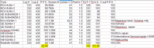
highlighted values are the averages. Not sure they are all that significant but here you go.
WB just means White Box. Sorting is more about the box than whats in the box. Last column is any other details.
Unrelated to anything, I did find that the Japan tubes are both prone to some 60hz hum which is extremely bad if the heater supply is left completely floating. Not sure how these would behave in the amp.
so for starters, this is the Mark IV schematic.
Changes to this just for completeness
The stuff in the red box is not there since this isn't a complete amplifier.
The 270K resistors go to ground, not to a negative bias supply.
The 620 + 47 resistors in the cathode chain have been replaced with a single 680 ohm resistor.
The highlighted 1.5M screen resistor has been replaced with a 470K + 1M pot.
The 82pf + 18K shelf network is not installed.
None of those changes should affect the results in a meaningful way but I'm trying to be transparent here.
Here are the results. Not sure it means a ton, but the screen resistor value to get max output is quite different, ranging from 780K to 1.3M. Values either side of optimal produce clipping or visible distortion on one side of the waveform and overall less output.
Voltage output is peak to peak measured to ground. Grid to grid would be double this. An ST-70 or Mark IV needs about 70 volts grid to grid, the worst tube here is capable of 270 volts so there is a huge amount of headroom which makes this not completely critical. Fair guess if you stick a 1M in there, it'll work well enough with most tubes.
Just as a mention though, GE#2, the one that wants the smallest screen resistor, when set to 1.5M the best I can get out of it with no visible waveform distortion is about 10v p-p, which is well below the point that is needed for max clean output in this circuit. Beyond that it has an overly fat shape to the negative peak, so some tubes are absolutely not going to play nice with stock values here. At 1M this tube will do 100v p-p which is plenty
If you want to get it closer to optimized without actually bothering to measure per-tube, subbing the 1.5M for a resistor + pot arrangement and adjusting it to get 332 volts at pin 1 would likely get you there. 332v is just the average of all voltages in my little selection here, but its also the value with the least variation % wise.
Voltages at lugs 6 and 8 were determined by working backwards from the voltage chart in the Mark IV manual. Power supplied from a Heathkit PS-2 to lug 8, and a 47K dropping resistor to a 22uF cap for pin 6, also duplicating the Mark IV circuit.
highlighted values are the averages. Not sure they are all that significant but here you go.
WB just means White Box. Sorting is more about the box than whats in the box. Last column is any other details.
Unrelated to anything, I did find that the Japan tubes are both prone to some 60hz hum which is extremely bad if the heater supply is left completely floating. Not sure how these would behave in the amp.


