
• The move to the new server is done. There are some software and database maintenance updates in process. This has us passing the hat around to help out. We appreciate any donations. Seriously, even a dollar helps. The payment page may be found here - https://www.audiokarma.org/support.html

9090db smokes R34 without fuse 04

Pilotlips

New Member
Hello,

Doing a restoration on the Sansui 9090db.
I did a full recap, changed most transistors, resistors, diodes and fixed all threw holes on the dolby board. Naturally also all pots/switches taken care of.
Now without the driver board using a dbt is dim the relay works and get the green protection light.
On the driver board 99% is new, also transistors gain matched but with the board connected the dbt is bright. I know usually this is a driver board transistor gone short (when I got the unit this was the case 2SA599) but all are now new and triple checked.
Now the funny part is with fuse 04 removed on the PS board only then R34 smokes away even with a dbt 70watt. Output transistors are new mj21193 and mj21194 and installed in the correct way. Could there be another problem else then the driver or power supply board or output transistors causing this failure?

So very stuck now, who can give a idea on how to bring 70's beauty back to life.

Thank you
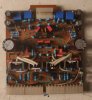
 

Attachments

  • IMG_20200123_214809__01.jpg
    IMG_20200123_214809__01.jpg
    64.2 KB · Views: 34
  • IMG_20200123_135254__01.jpg
    IMG_20200123_135254__01.jpg
    69.3 KB · Views: 33
Register to hide this ad
Have you checked R39, ZD02 and C10? I would also check the power supply circuit that connects to pin 18 on the driver board.

- Pete
 
D06 (originally a VD1212) on the right channel appears to be a single rectifier diode. It's usually two 1n4148 in series used as a replacement - not one. I'm not sure what's going on with D05 on the left channel but it appears different.
 
Hello,

Doing a restoration on the Sansui 9090db.
I did a full recap, changed most transistors, resistors, diodes and fixed all threw holes on the dolby board. Naturally also all pots/switches taken care of.
Now without the driver board using a dbt is dim the relay works and get the green protection light.
On the driver board 99% is new, also transistors gain matched but with the board connected the dbt is bright. I know usually this is a driver board transistor gone short (when I got the unit this was the case 2SA599) but all are now new and triple checked.
Now the funny part is with fuse 04 removed on the PS board only then R34 smokes away even with a dbt 70watt. Output transistors are new mj21193 and mj21194 and installed in the correct way. Could there be another problem else then the driver or power supply board or output transistors causing this failure?

So very stuck now, who can give a idea on how to bring 70's beauty back to life.

Thank you
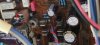
Make sure TR04 isn't in backwards. Also the silkscreen is backwards for D07/08. The band (cathode) goes toward the bottom (connector end)
 
Thank you for the tips so far,
R39 checked good C10 also.
ZD02 diode function was also good only I couldn't power it with more then 24v dc to test in reverse bias. i have to find a solution for this.
Pin 18 (and 15) provide steady -59v dc
Sorry not sharp photo D05&06 are 2x 1n4148 in series angled slightly different.
TR04 is mounted opposite to TR03 just like on the manual and silkscreen which I believe are correct here,and or isn't it?
D07/08 are facing down not like the screen.
I did notice now TR02 position the silk screen and manual are different but I've placed it like all other driver boards out there.
So I'm left with suspect zener pretty much the only thing I didn't replace,will come back to you.
 
TR04 is mounted opposite to TR03 just like on the manual and silkscreen which I believe are correct here,and or isn't it?
...
I did notice now TR02 position the silk screen and manual are different but I've placed it like all other driver boards out there.
Careful with the differential's pinout (TR01...TR04). It depends on what you're using. Which are these?
 
New zener installed and no difference.
In stead of C1400 im using KSC1845 with a high gain E C B pinout.
With also the driver board installed and dbt it is shinning bright. (FM receiver doesn't light up)
I tried without dbt everything lights as normal and got the green protection light.
After about 30seconds relay click with flashing red and measured 3v dc on the right speaker out, I wasn't quick enough to turn down the dc got a flash back side of the output transistors, results show 3x blown output transistors right channel and fuse 01&02 blown. Also the output transistors where very warm.
 
Now the funny part is with fuse 04 removed on the PS board only then R34 smokes away even with a dbt 70watt.

You are aware that F04 and F05 are wrongly marked on the power supply pcb? Looking from the front of the unit the left fuse feeds the left channel and vice versa...
 
New zener installed and no difference.
In stead of C1400 im using KSC1845 with a high gain E C B pinout.
With also the driver board installed and dbt it is shinning bright. (FM receiver doesn't light up)
I tried without dbt everything lights as normal and got the green protection light.
After about 30seconds relay click with flashing red and measured 3v dc on the right speaker out, I wasn't quick enough to turn down the dc got a flash back side of the output transistors, results show 3x blown output transistors right channel and fuse 01&02 blown. Also the output transistors where very warm.
You have some serious issues and have to start from scratch. Make damned sure the output transistors are in their correct positions. NEVER leave it on when the DBT is bright. Figure out why it is bright first. High DC offset itself won't cause a bright DBT without a load (dummy load or speaker load). Also, where are you getting your parts from?
 
Just a bit lost where to start looking, I have only basic knowledge of electrics learning on the go.
I do have a dummy load connected 200w 8ohm one left one right channel. Parts are from everywhere,
All caps mousers usa transistors upgraded to new versions I used AK to get info.
I do use a few "original" bought new
C945 and A733 transistors
And on the driver D381 & B536 bought new same as original, are these fake?
I remember now VR03&04 for the bias current are supposed to be 100ohm on this gen 2 board and I used 200 ohm 25 multi turn. When Installing I set the same resistance as the trim pots that came out still could this be a problem giving to much current to the output transistors?
 
Just a bit lost where to start looking, I have only basic knowledge of electrics learning on the go.
I do have a dummy load connected 200w 8ohm one left one right channel. Parts are from everywhere,
All caps mousers usa transistors upgraded to new versions I used AK to get info.
I do use a few "original" bought new
C945 and A733 transistors
And on the driver D381 & B536 bought new same as original, are these fake?
I remember now VR03&04 for the bias current are supposed to be 100ohm on this gen 2 board and I used 200 ohm 25 multi turn. When Installing I set the same resistance as the trim pots that came out still could this be a problem giving to much current to the output transistors?
Do NOT have a dummy load or speakers hooked up. It even says that in the service manual. Depending on where you bought the transistors, chances are high they were counterfeit (fake). There are modern substitutes that work just fine available at Mouser, or Digi-Key, and other trusted distributors. If the POTS are supposed to be 100 Ohm, use 100 Ohm. 200 Ohm will upset the differential and adjustment range and make it harder to adjust. But don't feel bad, many people have been "duped" buying obsolete components that turned out to be fakes. FleaBay and Amazon are full of fakes. There is no need to buy "original" 2SA733 since you can buy new, and better KSA733C. Same with 2SC945 when you can buy KSC945C. The C is important too since it means C)enter Collector for both. You didn't mention what output transistors you used. But if you bought "new and original" ones, you might as well toss them all. Modern ON Semi are better than the originals in this unit anyways. But you'll need all 8, 4 PNP and 4 NPN. You have your work cut out for you. Perhaps it would be a good idea to find someone in your area that knows how to service these vintage Sansui. Where are you from?
 
Just a bit lost where to start looking, I have only basic knowledge of electrics learning on the go.
I'm so sorry for this accident. I wanted to ask about bias current readings on Wednesday but I've decided against stating the obvious. I had no idea about your qualifications so I just assumed it was OK. Unfortunately with an overshooting bias current or short circuit related accidents that results in blown output transistors the extent of the collateral damage is typically too wide to be addressed by anyone who is less than a seasoned DIY'er. AK can give the wrong impression when some of the best techs in the country makes elaborate electronics troubleshooting sound like a walk in the park. The truth is that even the seemingly benign recap of a vintage unit can easily turn sour. It is my opinion that the best course of action right now would be to get the unit as is to an experienced vintage tech, explain the history, and let them take over to save this unit.
 
For the time being, you don't have to connect the power transistors to trouble shoot your issues to save them from further damages. The driver board is the voltage gain stage and the power transistors are power gain stage.

There could be many possible causes of the issues as many components have been changed.

The service manual is not very helpful as there are only very few voltage marked on the circuit nodes. But rough estimate is still possible with a calculator and tracking the circuit.

Here are few things I would start with:

1. Measure voltage between R18 and R38 to see if it's -25.5V (the circuit shows 25.5V, I think it's a typo missing the minus sign as the base of TR04 should be around zero volt and if it's +25.5V, the differential pair will be highly reversed bias).
2. Measure voltage between emitter of TR12 and 14 to see if it's around 1.2 V.
3. Adjust VR04 to see if the voltage in step 2 can be changed. If it can be changed, adjust to minimize the voltage.
4. Measure voltage across the base of TR12 and 14 to see if it's around 2.4V. It should be if step 3 is good.
5. Measure the voltage across R32 to see if it's about 0.6V
6. Measure the voltage across R22. Is it about 0.6V?

Note that I got the component number from one of the power amp. Do the same for the other channel.

The above steps should give us some clues on the root cause of the problem.

Good luck.
 
Also check if C08 was installed reversed and has a voltage rating higher than 63V as R34 was smoked but not R33.

Also check possible solder bridges that could short out circuits...

Do you have a variac? it would be handy here....
 
Do you have a variac? it would be handy here....
In my opinion a DBT is the best tool for this issue, providing it is used correctly, conversely, in my opinion a Variac is not much use at all.

It is impossible for a Variac to compete with 'instantaneous & automatic' current limiting provided by a DBT.
 
[QUOTE="Hyperion, post:

Rule 1.
Never connect a unit that shows a bright DBT bulb directly to the mains - never ever. - That's what a DBT is for! - to warn you of an 'issue'. :([/QUOTE]

Thank you I will follow this advice.
 
Do NOT have a dummy load or speakers hooked up. It even says that in the service manual. Depending on where you bought the transistors, chances are high they were counterfeit (fake). There are modern substitutes that work just fine available at Mouser, or Digi-Key, and other trusted distributors. If the POTS are supposed to be 100 Ohm, use 100 Ohm. 200 Ohm will upset the differential and adjustment range and make it harder to adjust. But don't feel bad, many people have been "duped" buying obsolete components that turned out to be fakes. FleaBay and Amazon are full of fakes. There is no need to buy "original" 2SA733 since you can buy new, and better KSA733C. Same with 2SC945 when you can buy KSC945C. The C is important too since it means C)enter Collector for both. You didn't mention what output transistors you used. But if you bought "new and original" ones, you might as well toss them all. Modern ON Semi are better than the originals in this unit anyways. But you'll need all 8, 4 PNP and 4 NPN. You have your work cut out for you. Perhaps it would be a good idea to find someone in your area that knows how to service these vintage Sansui. Where are you from?

I just bought some bourns 25 turn 100ohm and will hunt for modern not fake transistors replacements.
Output I got MJ21193 and MJ21194 ON and bought some extras so I could gain match a pair. When I got the unit right channel 4x original Toshiba left 3x TIC rated 100w and 1 fake Toshiba.
I currently live in Berlin Germany there might be a tech nearby but for now I want to continue learning and figure it out for me half the fun is the repair/rebuild.
 
Back
Top Bottom