• The move to the new server is done. There are some software and database maintenance updates in process. This has us passing the hat around to help out. We appreciate any donations. Seriously, even a dollar helps. The payment page may be found here - https://www.audiokarma.org/support.html

A-1000 Rehab: DC voltage in signal path SOLVED

Hmm. TR121 is good at B and E (~50V each), but is at -30V from the collector (should be -1.8V). It tests fine on the multimeter.

 
D121 (HZ16-3L Zener): 4.75V across it. -35V at anode / TR119E. Not good either.
Replace
D111 (HZ9C-3 9.1V Zener): 0.15V across it, but -36V cathode to -35.3V anode.
Replace
D109 (HZ9C-3 9.1V Zener): 5V across it. -35.5V anode to -30.5V cathode.
Replace
D107 (1S1555): Tests good, -35.5V anode to -30.5V cathode .
Bad -- Should only be .6 volt difference -- Replace with 1N4148
 
Last edited:
R183 verified OK (4.4k), R163 verified OK ... however. +50V on one side, -13V on the other side. This is TR115C as measured earlier. Hmm.

Edit: Noted on diodes! Thanks.

Do both ends of that resistor have 50 volts on them ?
Yes both ends.

Did you replace C173 680µf/85vdc ?

Yes with new (shown in one of the pics I put up this morning).
 
Last edited:
Do you think I should re-solder all of the OPTs and voltage amplifiers back down before proceeding with the diagnosis?
 
I'd replace those diodes before trying to T-shoot any further.
 
Thanks - will do.

I wonder if I could just swap them between channels for now?

Also - I have successfully found a silver button cover for my missing Phono button, finally. The funny part, it actually did come from an A-2000 that was getting parted out! We were joking about that earlier in the thread.
 
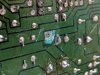
Looky what I found between C173+ and D113A. The entire path corroded from corrosion seeping through a hole in the PCB from the topside. That's why D113 etc. wasn't getting +HB voltage.

I cleaned it up, scraped some new contact patches on both sides, soldered a bridge, and now I have 0V on both channels.

I am still not hearing a protection click, however.

Next step is to solder everything back down and see if it comes out of protection. In the meantime add those diodes to my BOM

.IMG_20190916_193920.jpg
 
I finished the recap other than being short by two bipolar 22uFs (there are four 22uF bipolars used ... C617/C618 on the vertically mounted Equalizer (1) board with the input jacks, and C655/C656 on the Equalizer (2) board with the tone controls). So I left C655/C656 in for now (each measures about 150% original spec at ~35uF), will order them.

... almost got away with it. It's reeling me back in. Turned it on after the recap (through the DBT), POP, copious smoke from the back right near the RCA inputs. Upon inspection, C127 is bulging and may have popped out the top. I used a Nichicon FG 100uF / 10V cap. The polarity is correct.

After the pop, I am measuring negative DC voltage on both channels (-16V, -18V).

It seems like it must be something I did during the re-cap, since it was fine before. Not sure what yet. Sigh. Time to put the diagnosis hat back on.
 
Last edited:
Back
Top Bottom