Sigurdik
New Member
First of all let me thank all the people around the HiFi globe for caring and sharing thought, knowledge and ideas with the communities. Without them this project would not have been realised with this high level of enjoyment and quality.
In particular my thanks goes to Yazaki-san, for sharing his knowledge about modifying Marantz 7c and building DHT amplifiers through his excellent articles at Jeff`s place.
I also want to mention J.P. Hans van Vliet for sharing his knowledge about EMT 139st (my next project), and also @tubeactive at this very page for sharing RIAA calculation and Shure M65 together with @setup1. This gave my Neumann WV2 the final touch and crowned the whole thing.
For a long time I have wanted to build myself a phono preamplifier to company my heavily modified Space Audio WE91B and Altec 604E Alnico. I have searched and investigated what to build.
Initially I thought of the Marantz 7C phono section because of Yazaki-san`s excellent article, and it made a lot of sense. The M7C have been highly phrased for it`s build and high quality, and I see that many people that i admire in the audio world swear to it. I have even started to collect the components needed.
Then I became aware of the EMT 139st through mr. Vliets page, I have also noticed that vintage EMT record players are very sought after, so I thought that the 139st must be a even better choice than the M7C.
But by chance I became aware of the Neumann WV2..... again through mr Vliet`s postings.
If my investigation are right, this phono preamplifier was actual not sold as a standalone unit, but was developed to be used inside Neumann`s vinyl cutting machines for evaluating the final vinyl master, so I figured out that this MUST be the HOLY GRALE of all vintage phono preamplifiers. The fact that there is not much information on the web about it, and that the original items that i have found for sale goes for as much as $10.000 in Asia, in addition the cathode bias is set with batteries. It has to be good and my curiosity rised even more.
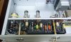
So i googled and collected as much information as I could, and finally decided to go for it.
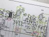
Mono @ Stereo posted an article about mr Vliet`s Neumann WV2 project. This was the first schematics i acquired. After some more searching i got hold of some good resolution and complete drawings on Groupe DIY site. This was very helpful to understand the components that was a part of the active RIAA network.

The next drawing, I found on groupediy.com and was in a higher resolution and showed the complete schematics, with filtering caps and all.
So first I had to isolate the phono section. And since i also would like to use it with my beloved Shure V15-III MR i needed to stripp away the MC transformer as well.
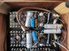
I collected the needed components for the project, NOS Telefunken tubes, TAKMAN and Alen Bradley resistor, 1.2V batteries, the rest of the components I already had from earlier upgrading projects.
So I started to build a prototype as a "birds nest".
Welcome "the CROW"
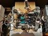
The initial listening test was a disaster, no sound, only high quality HUM...
So i studied the schematics again and decided to try to remove the R13/14 resistor. I am not quite sure, but i believe this is to lift the ground. I also removed the R11/12. And R9/10 was set to 47k as you would expect in a MM phono section. Well, anyway that cured the no sound part. The second listening test was VERY promissing!!!
Deep and articulated bass, good depth and with in the sound stage, spacial, but with some remaining issues. Motorboating was one, hum was a second.
Some late night google search taught me about grid stopper resistor, so a 3k resistor soldered directly on the grid of the first tube solved most of the motorboating issue, i could stil hear it, but it was faint. The next problem in the CROW nest was the hum. This I almost solved with paying attention to cable routing, so tyding up the nest a little helped, but did not take it away the hum completely.
Next step was to give the CROW a descent home, so i purchased a Hammond walnut chassis, Hammond transformer and choke. The bird was ready to move in.
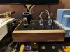
Next problem arrived
I got the right transformer with the right high voltage and plenty of power for the 6.3v heaters, BUT the 5v for the 5U4G rectifier tube i was planning to use was only 2A and not the needed 3A. So some more google and i found out that the 5AR4 had the same pin configuration, but only needed 2A. Order was placed and the tube collected at a local guitar shop.
So how to wire the transformer, choke and capacitors. There are a ton of ways to do it, and my first attempt resulted in... yes you guested it, HUM
More google and by chance i stumbled upon an excellent description at emitionlab`s web page. So this I followed with an almost perfect result, but still some HUM, and the motorboat had returned, but at a lower level than before.
OK, that had to wait, I WANTED TO LISTEN TO MUSIC.
And music there was. VERY promissing. Large sound stage, DEEP bass, but still room for improvement.
I have always admired Shindo equipment, and have read all the reviews I could find, studied their interior on every picture, and learn about their history. Especially the articles by Art Dudley in Stereophile and his Listening series have intrigued me. So much information a part from that he also is an excellent writer.
In on of the Shindo photographs i saw how they solved the grounding in their newer amplifiers. A lot of separate ground wires to one common ground as close to the phono grounding lug as possible.

Of course i had paid attention to only having one grounding point, just as Emissionlabs had described in their article, but i had taken a shortcut. I measured the bolt from the transformer and made sure it had contact with the chassis and then chosen this as the grounding point, to save time. Yeah Right.
Stripp all the grounding wire, make a new central grounding point at the phono grounding lug, strip of the chassis paint to make sure the contact is perfect, so basically, do it the right way, the Shindo way.
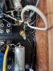
And as if by a stroke of magic... The motorboat has left the port, and dead quiet, no hum.
In my next post I will share my experience of selecting component for the different part of the amplifier, some adjustments and the final reworked schematic that I ended up using.
Best regards
Sigurd
In particular my thanks goes to Yazaki-san, for sharing his knowledge about modifying Marantz 7c and building DHT amplifiers through his excellent articles at Jeff`s place.
I also want to mention J.P. Hans van Vliet for sharing his knowledge about EMT 139st (my next project), and also @tubeactive at this very page for sharing RIAA calculation and Shure M65 together with @setup1. This gave my Neumann WV2 the final touch and crowned the whole thing.
For a long time I have wanted to build myself a phono preamplifier to company my heavily modified Space Audio WE91B and Altec 604E Alnico. I have searched and investigated what to build.
Initially I thought of the Marantz 7C phono section because of Yazaki-san`s excellent article, and it made a lot of sense. The M7C have been highly phrased for it`s build and high quality, and I see that many people that i admire in the audio world swear to it. I have even started to collect the components needed.
Then I became aware of the EMT 139st through mr. Vliets page, I have also noticed that vintage EMT record players are very sought after, so I thought that the 139st must be a even better choice than the M7C.
But by chance I became aware of the Neumann WV2..... again through mr Vliet`s postings.
If my investigation are right, this phono preamplifier was actual not sold as a standalone unit, but was developed to be used inside Neumann`s vinyl cutting machines for evaluating the final vinyl master, so I figured out that this MUST be the HOLY GRALE of all vintage phono preamplifiers. The fact that there is not much information on the web about it, and that the original items that i have found for sale goes for as much as $10.000 in Asia, in addition the cathode bias is set with batteries. It has to be good and my curiosity rised even more.
So i googled and collected as much information as I could, and finally decided to go for it.
Mono @ Stereo posted an article about mr Vliet`s Neumann WV2 project. This was the first schematics i acquired. After some more searching i got hold of some good resolution and complete drawings on Groupe DIY site. This was very helpful to understand the components that was a part of the active RIAA network.
The next drawing, I found on groupediy.com and was in a higher resolution and showed the complete schematics, with filtering caps and all.
So first I had to isolate the phono section. And since i also would like to use it with my beloved Shure V15-III MR i needed to stripp away the MC transformer as well.
I collected the needed components for the project, NOS Telefunken tubes, TAKMAN and Alen Bradley resistor, 1.2V batteries, the rest of the components I already had from earlier upgrading projects.
So I started to build a prototype as a "birds nest".
Welcome "the CROW"
The initial listening test was a disaster, no sound, only high quality HUM...
So i studied the schematics again and decided to try to remove the R13/14 resistor. I am not quite sure, but i believe this is to lift the ground. I also removed the R11/12. And R9/10 was set to 47k as you would expect in a MM phono section. Well, anyway that cured the no sound part. The second listening test was VERY promissing!!!
Deep and articulated bass, good depth and with in the sound stage, spacial, but with some remaining issues. Motorboating was one, hum was a second.
Some late night google search taught me about grid stopper resistor, so a 3k resistor soldered directly on the grid of the first tube solved most of the motorboating issue, i could stil hear it, but it was faint. The next problem in the CROW nest was the hum. This I almost solved with paying attention to cable routing, so tyding up the nest a little helped, but did not take it away the hum completely.
Next step was to give the CROW a descent home, so i purchased a Hammond walnut chassis, Hammond transformer and choke. The bird was ready to move in.
Next problem arrived
I got the right transformer with the right high voltage and plenty of power for the 6.3v heaters, BUT the 5v for the 5U4G rectifier tube i was planning to use was only 2A and not the needed 3A. So some more google and i found out that the 5AR4 had the same pin configuration, but only needed 2A. Order was placed and the tube collected at a local guitar shop.
So how to wire the transformer, choke and capacitors. There are a ton of ways to do it, and my first attempt resulted in... yes you guested it, HUM
More google and by chance i stumbled upon an excellent description at emitionlab`s web page. So this I followed with an almost perfect result, but still some HUM, and the motorboat had returned, but at a lower level than before.
OK, that had to wait, I WANTED TO LISTEN TO MUSIC.
And music there was. VERY promissing. Large sound stage, DEEP bass, but still room for improvement.
I have always admired Shindo equipment, and have read all the reviews I could find, studied their interior on every picture, and learn about their history. Especially the articles by Art Dudley in Stereophile and his Listening series have intrigued me. So much information a part from that he also is an excellent writer.
In on of the Shindo photographs i saw how they solved the grounding in their newer amplifiers. A lot of separate ground wires to one common ground as close to the phono grounding lug as possible.
Of course i had paid attention to only having one grounding point, just as Emissionlabs had described in their article, but i had taken a shortcut. I measured the bolt from the transformer and made sure it had contact with the chassis and then chosen this as the grounding point, to save time. Yeah Right.
Stripp all the grounding wire, make a new central grounding point at the phono grounding lug, strip of the chassis paint to make sure the contact is perfect, so basically, do it the right way, the Shindo way.
And as if by a stroke of magic... The motorboat has left the port, and dead quiet, no hum.
In my next post I will share my experience of selecting component for the different part of the amplifier, some adjustments and the final reworked schematic that I ended up using.
Best regards
Sigurd
Last edited: