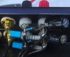
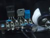
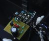
I don't get it. I got this very unusual, very spartan high end hybrid tube amp in with the complaint: blows its fuses. The patient is a Croft Acoustics Phono Integrated amplifier. It got some rave reviews across the internet and of course it is reassuringly expensive. My amp was bought second hand and promptly blew its fuse when the buyer hooked it up at his home after a successful demo.
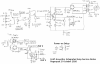
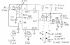
I've requested the service manual/schematic but I have yet to hear back from the maker. This amp is unusual in that it is point-to-point wired using terminal strips as anchor points. It is also unusual in that the gain stage is a single half ECC83 followed by a 2SJ162/2SK1058 MOSFET pair as buffer with another MOSFET thrown in for good measure. Refer to the attached reverse engineered schematic.
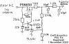
Now I see two serious design flaws. The first one is causing the fuses to blow. There is a crow bar across the speaker terminals in the form of a triac. I think the idea is that when DC appears at the output it gets triggered blowing the fuses. Now look closely at the capacitor and resistor connected to its gate. Shouldn't they be swapped? This is what happened: I had a DBT hooked up, time delay expired, DC offset got via the big 2200 µF cap into the gate, boom. My DBT prevented the fuse being blown again.
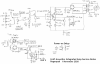
The second flaw is really puzzling me. A tube amp gain stage needs a really, really quiet power supply. This one isn't. There is almost a volt AC ripple riding on the supply voltage. What is this circuit supposed to do? It certainly isn't getting rid of the ripple. Nor is it doing any stabilizing.
So my idea is to swap the crow bar components and fix the power supply by adding a 200 V zener to ground and ditching the LM317. Is this a sound idea or am I missing something?
I've requested the service manual/schematic but I have yet to hear back from the maker. This amp is unusual in that it is point-to-point wired using terminal strips as anchor points. It is also unusual in that the gain stage is a single half ECC83 followed by a 2SJ162/2SK1058 MOSFET pair as buffer with another MOSFET thrown in for good measure. Refer to the attached reverse engineered schematic.
Now I see two serious design flaws. The first one is causing the fuses to blow. There is a crow bar across the speaker terminals in the form of a triac. I think the idea is that when DC appears at the output it gets triggered blowing the fuses. Now look closely at the capacitor and resistor connected to its gate. Shouldn't they be swapped? This is what happened: I had a DBT hooked up, time delay expired, DC offset got via the big 2200 µF cap into the gate, boom. My DBT prevented the fuse being blown again.
The second flaw is really puzzling me. A tube amp gain stage needs a really, really quiet power supply. This one isn't. There is almost a volt AC ripple riding on the supply voltage. What is this circuit supposed to do? It certainly isn't getting rid of the ripple. Nor is it doing any stabilizing.
So my idea is to swap the crow bar components and fix the power supply by adding a 200 V zener to ground and ditching the LM317. Is this a sound idea or am I missing something?