• The move to the new server is done. There are some software and database maintenance updates in process. This has us passing the hat around to help out. We appreciate any donations. Seriously, even a dollar helps. The payment page may be found here - https://www.audiokarma.org/support.html

Absolutely butchered 250M

goldswimmerb

Failed out of engineering, but look at me now!
Subscriber
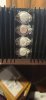
Just got this beast on the bench, going to be a hell of a project for sure.

Non matching outputs (who though throwing a phase linear custom in here was a good idea???)received_288082172490810.jpegreceived_1223855914622845.jpeg don't even know what's going on here.
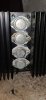
Side with phase linear Transistor is unplugged, guessing it's fried, other side with the mix of Transistors shows 100+MV on the bias...
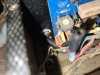
20200812_220524.jpg
Broken transistor lead on the bias Transistor
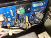
20200812_220516.jpg
Interesting driver choice + one Transistor has been cut and resoldered...

Whayddya think? Any hope of saving this guy?
 
Register to hide this ad
That actually doesn't look that bad.

The 250 amps are way more finicky/troublesome than the 250M when it came to hFE matching of predrivers,drivers, outputs and runaway bias.

I always renew all the outputs anyway with MJ21195/96(some like 21193/94- same thing but 95/96 are sometimes less expensive).

Renew all the electrolytics ,I always spring the extra $ for Vishay AML axials to keep oem look.

I try to use oem type TO66's for the driver's driver's but some others have found a way to kitbash TO220's there like in your pic.
The center lead is cut because the tab with screw is the collector.

Follow to a T the tech service bulletin on matching predrivers,drivers and outputs (which means you have to actually pull and test them).

Always renew,hFE match and heat shrink bond the differencial input pairs with new MPSA 2N5961 TO 92's (Mouser).

Buy the proper MPSA TO 92's rather than something else you have to cross the legs to make it work.

Make sure it has the proper bias transistor.
The 250's used a "block" style wired bias transistor but they switched to a more modern TO220 with a nice plug-in design on the 250M's.

The old way of setting bias in the service manual using a watt meter was proven to be a bad idea and was superceded by a later tech service bulletin checking bias MV the correct way via the emitter resistors.

Don't forget the flyback diode mod also addressed in a tech service bulletin.

Don't try and "clean/sand " the relay contact tips as they were silver plated and once that plating is gone you're down into soft copper.
Renew it with a modified Omron relay.

Renew the main filter caps ,new 24,000uf ones are available.(DigiKey 565-3679-ND)

Change the fuse style meter lamps to led to keep the plastic meter scale from further yellowing

Maybe more but that's all I remember off the top of my head.

Bob
 
Last edited:
Looks better than the one I just parted out....missing two driver heatsinks, the meter board, and driver board. With "bonus" fuses and speaker terminals!

Save it. I'm sure you know about the bullitens.
 
@goldswimmerb , looks like a fun project!

Tom

Yeah, been taking work from a local shop, guy just buys out lots of equipment, this came in with a dozen or so other decent pieces.
It's missing a bunch of screws, but the important ones are all there.

I also have an Audio Research D350 that was in the same lot of Equipment, hoping that one just needs caps as replacing all 64 output transistors in that thing would be terrible.
 
Ya, that doesn't look so bad.
Ask Bob to show you some pics of a 250 that I sent to him. It was in worse shape than yours, IMO. Bob spent good time on mine, repaired, refurbed and it now runs like a champ.
 
That actually doesn't look that bad.

Always renew,hFE match and heat shrink bond the differencial input pairs with new MPSA 2N5961 TO 92's (Mouser).

Buy the proper MPSA TO 92's rather than something else you have to cross the legs to make it work.

Bob

Was this a typo by chance? Which MPSA Transistors am I replacing? And I assume the 2N5961s are for my differential pair? Are there other transistors before the predrivers worth replacing, or if they work should I leave them? I actually have a few MPSA65 replacements in case I need them thanks to my local electronics store keeping old stock parts around.

Also, can someone explain how the transistor matching works? Service bulliten 2 and the manual seem to have several different ranges for different Transistors, am curious how these apply to modern Transistors. Like for Q507 I see the range of 70-140 and 140-160 and 150-300. What am I shooting for?
 
Alright, so I think I got my predrivers in the right HFE range (both were around 100).

I have seen people successfully use MJE15030/MJE15031 for the drivers. While I have these, my last batch of MJE15031s were in the 300-350hfe range, I assume that is too much? The 15030s we're pretty much perfect in the 120 or so range.
 
That actually doesn't look that bad.

The 250 amps are way more finicky/troublesome than the 250M when it came to hFE matching of predrivers,drivers, outputs and runaway bias.

I always renew all the outputs anyway with MJ21195/96(some like 21193/94- same thing but 95/96 are sometimes less expensive).

Renew all the electrolytics ,I always spring the extra $ for Vishay AML axials to keep oem look.

I try to use oem type TO66's for the driver's driver's but some others have found a way to kitbash TO220's there like in your pic.
The center lead is cut because the tab with screw is the collector.

Follow to a T the tech service bulletin on matching predrivers,drivers and outputs (which means you have to actually pull and test them).

Always renew,hFE match and heat shrink bond the differencial input pairs with new MPSA 2N5961 TO 92's (Mouser).

Buy the proper MPSA TO 92's rather than something else you have to cross the legs to make it work.

Make sure it has the proper bias transistor.
The 250's used a "block" style wired bias transistor but they switched to a more modern TO220 with a nice plug-in design on the 250M's.

The old way of setting bias in the service manual using a watt meter was proven to be a bad idea and was superceded by a later tech service bulletin checking bias MV the correct way via the emitter resistors.

Don't forget the flyback diode mod also addressed in a tech service bulletin.

Don't try and "clean/sand " the relay contact tips as they were silver plated and once that plating is gone you're down into soft copper.
Renew it with a modified Omron relay.

Renew the main filter caps ,new 24,000uf ones are available.(DigiKey 565-3679-ND)

Change the fuse style meter lamps to led to keep the plastic meter scale from further yellowing

Maybe more but that's all I remember off the top of my head.

Bob

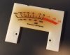
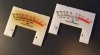
I am noticing that my meters are pretty greened, is there a way to fix that?
 
Sadly it's the actual white plastic dial face that is yellowed from incandescent lamp heat.

It's the same effect that you see with the old yellowed vellum in Marantz receivers.

I asked an AK member who makes absolutely spot on replacement lamp housings and he can make the plastic piece but not the silk screen dial scale printing with the two colors.

Maybe someone else can give it a go.


lk55y1b.jpg


ZZ7f6vC.jpg


Bob
 
Last edited:
I have seen people experiment with color filters to correct dial/meter colors when they couldn’t remove the brown. The opposite of brown on the color wheel is medium blue. It might be worth getting some gel type filters and experimenting. The thought of green meters on a Marantz makes me ill. :eek:
 
What about one of the bluish LEDs instead? Would it be enough to offset the yellowed meter face?
 
I have seen people experiment with color filters to correct dial/meter colors when they couldn’t remove the brown. The opposite of brown on the color wheel is medium blue. It might be worth getting some gel type filters and experimenting. The thought of green meters on a Marantz makes me ill. :eek:
They're not that terrible, but they're noticibly greener and darker than the ones in my personal 250m, going to try some cool white LEDs instead of warm white as the warm white uses yellow to achieve the "warmness" which is probably contributing to the issue.
 

Attachments

  • IMG_20200821_154826_768.jpg
    IMG_20200821_154826_768.jpg
    89 KB · Views: 45
Sadly it's the actual white plastic dial face that is yellowed from incandescent lamp heat.

It's the same effect that you see with the old yellowed vellum in Marantz receivers.

I asked an AK member who makes absolutely spot on replacement lamp housings and he can make the plastic piece but not the silk screen dial scale printing with the two colors.

Maybe someone else can give it a go.


lk55y1b.jpg


ZZ7f6vC.jpg


Bob

I restored a Marantz Model 510M about 8-10 years ago, it was an 18 months project.

In the end, I had a beautiful and 100% working amp, which I have used on and off since then. The only problem after this 18 months project was the
meters, which looked like this, it is one of the actual dials, pulled from my Model 510M:


Marantz 510M dial - 1.jpg

Totally disappointing to look at . . . . .

By the way, it looks as if the measurements are of the Model 250M and Model 510M dials are the same, I have checked with the measurements
above. I did try to clean the dials, but was told by a plastic expert, that the colour changes was caused by the heat from the bulbs, which made the dial
material turn brown all the way through.

I did a lot of thinking . . . . . . .

In the end, I had all new dials made, material colour, all measurements totally like the originals, black writing non transparent and red writing transparent,
all like the originals. Now looking like this:

Marantz 510M dial - 2.jpg


The rest was a straight forward screwdriver job, - but do take care of the dial fingers . . . . . . !!!!!
I had a number of extras made, - was it expensive?? YES!!!! REALLY!!!!
But it made my Model 510M look like this, sorry about the little blurry picture.


Marantz 510M dial - 3.jpg


It was really worth it, because it made the restoration complete.

Regards
NikonSP
 
Hi folks, good evening.
In regards of the post about the VU dials. I can highly recommend member NikonSP, he is a very correct and honest seller and personal friend.

I have seen with my own eyes what he did with his personal 510M, and the new ones were stunning to replace his burned old ones. He has some more, but it is up to him to decide if he wants to sell them.
I hope he can help you further with your restoration...

ancien (aka Marantz History)
 
I restored a Marantz Model 510M about 8-10 years ago, it was an 18 months project.

In the end, I had a beautiful and 100% working amp, which I have used on and off since then. The only problem after this 18 months project was the
meters, which looked like this, it is one of the actual dials, pulled from my Model 510M:


View attachment 1963056

Totally disappointing to look at . . . . .

By the way, it looks as if the measurements are of the Model 250M and Model 510M dials are the same, I have checked with the measurements
above. I did try to clean the dials, but was told by a plastic expert, that the colour changes was caused by the heat from the bulbs, which made the dial
material turn brown all the way through.

I did a lot of thinking . . . . . . .

In the end, I had all new dials made, material colour, all measurements totally like the originals, black writing non transparent and red writing transparent,
all like the originals. Now looking like this:

View attachment 1963070


The rest was a straight forward screwdriver job, - but do take care of the dial fingers . . . . . . !!!!!
I had a number of extras made, - was it expensive?? YES!!!! REALLY!!!!
But it made my Model 510M look like this, sorry about the little blurry picture.


View attachment 1963091


It was really worth it, because it made the restoration complete.

Regards
NikonSP

Sent you a message before I realized you had already posted here. How much did they cost to get made? Would be willing to buy a set of it's not too insane.
 
Having a hard time with my right channel, testing without outputs I see 1.1v on my collector of Q508 and .8v on my collector of Q507. Not sure what's happening
 
Now at about 1v on both my collectors (Q508 and Q507). Drivers get really hot. No clue where the extra voltage is coming from...
 
What did you use for differencial input transistors?
Did you use TO66'S for drivers or swapped in TO220s?
Did you use new mica under the drivers and properly install them?


Bob
 
Back
Top Bottom