• The move to the new server is done. There are some software and database maintenance updates in process. This has us passing the hat around to help out. We appreciate any donations. Seriously, even a dollar helps. The payment page may be found here - https://www.audiokarma.org/support.html

ACCUPHASE E-205 HELP NEEDED

Joan Biel

New Member
Hi all, I have just purchased an Accuphase E-205 which apparently has a channel with the output transistors having problems.
The other channel seems to have been fixed previously.

I would like to know if someone could help me to make it functional.

1. Help me know if the modified channel could be better.

2. Advise me how to proceed with the channel that is not working right now.

I have done a first check on the transistors and it seems that the MOS FET has a short. I have reviewed amplifier, but never of these characteristics, I hope you can help me.

Many thanks as always. This community is amazing.

best regards

John Biel
 
Register to hide this ad
Hi John, you might want to ask a moderator to change the name under your avatar to John as it currently says "JOAN".

Are you familiar with testing transistors for shorts? Is the (so called) modified channel working? If so, it is possible the previous owner just used substitute transistors for the originals and it probably has not been modified as that would take an extensive knowledge of electronics and circuits.

If you know for sure that the transistors (MOSFET's) in the other channel are shorted, then probably get the same one's like those that are in the good working channel. You will also need to check other transistors ahead of the outputs like the drivers and emitter resistors.
 
Hello Joan (or John ? )

1) there is no mosfet in power stage output , they are bipolar normal power transistors 2SB863 and 2SD1148
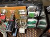
2) there is a FET in TO220 package for TR2SJ76 (green transistor) Q17 and for Q16 is 2SK213 FET (in black) TO220 package . Q16 and Q17 are driver transistors
3) at the input of this power stage you will find a 2SK389 double FET in the same package . This double transistor is sometime the first you should check if they are OK or not
4) emitor are 0,22 ohm /2W 10%
 
First of all, thank you for giving time to others for free.

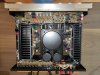
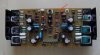
This weekend if I find time I will do the checks you said and post the results, I will also add pictures of both channels.

Yes, I've fixed other amps before, but since this is a more expensive amp and I want it to look as good as possible, I'd like advice from more experienced people. I want to leave it as good as possible and rectify possible mistakes made in the past (if there are any).

I hope we can all fix it!!!

Thanks

PS: my name is JOAN BIEL, I'm from Mallorca.
 
Thanks for replying cademan, really appreciate your help.

The amplifier will be in protection only with the two channels connected, with the one that has already been modified the amplifier comes out of protection.
So my first thought was to do the same thing that was done with the broken channel.
But i asked for help because i want to get off accuphase as best as possible.
 
Hello Joan (or John ? )

1) there is no mosfet in power stage output , they are bipolar normal power transistors 2SB863 and 2SD1148
2) there is a FET in TO220 package for TR2SJ76 (green transistor) Q17 and for Q16 is 2SK213 FET (in black) TO220 package . Q16 and Q17 are driver transistors
3) at the input of this power stage you will find a 2SK389 double FET in the same package . This double transistor is sometime the first you should check if they are OK or not
4) emitor are 0,22 ohm /2W 10%

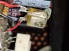
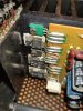
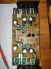
You mean this one?
IMG_20221018_123944.jpg
 
You really need to get an ohm meter and learn how to use it. A DVM is a repair persons best friend and can help find almost every type of discrepancy aside from getting and using a scope.
 
You really need to get an ohm meter and learn how to use it. A DVM is a repair persons best friend and can help find almost every type of discrepancy aside from getting and using a scope.
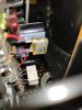
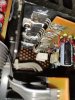
I have a tester, and I know how to check ohms. I have to find time and do the necessary checks. In the following photo you can see the modification made, what function does the component indicated? thanksIMG_20221018_230639.jpg
 
That is a capacitor and you need a schematic to see what it does in the circuit. It was probably added to cut oscillations or ringing in the circuit. I wouldn't worry about it at the moment but rather any shorts in any of the output transistors.

Then again, take your meter and set it to DC 200 volts on the voltage setting and take voltage measurements of the good channel compared to the bad channel and see where the voltage stops. That will most likely be your problem area.
 
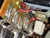
The resistor seem to be burnt.

Readings:

Q20
B to C short
B to E open
E to C 543
E to B 543
C to B short
C to E open


Q18
Same as Q20

Are both D1148 bad??
 
i already have news with my accuphase, i changed the right channel power transistors and now everything seems to be working fine. there is no way to find the settings for this amp, can someone tell me how many millivolts should I leave the setting? thank you all very much John Biel
 
Back
Top Bottom