

Hi everyone!
I completely recapped the Accuphase P-266. Once the amplifier is on, it runs great! But charging 4x 22,000uF filter capacitors causes a high inrush current.
Every time I first start it, the circuit breaker is trips because the inrush current is too high. This also happened before restoring the amplifier.
The 10A fuse, which is installed in the amplifier, never blows, which is good! So it makes me think that the circuit breaker is old and is set off easily.
Regardless, I would like to explore the possibility of reducing the inrush current so that the circuit breaker does not trip every time I attempt to power the amplifier. According to some research I did, this can be mitigated using an NTC and a relay which I think the amplifier already has. But it doesn't seem to do too good of a job in reducing the inrush current.
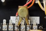
This is the NTC (or a capacitor?) that is currently in the amplifier:
For more information, the only relay I have not replaced in this amplifier is this one:
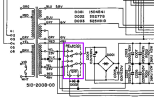
I am guessing this relay is combined with the NTC to limit the inrush current, but I am not sure. Does someone know the purpose of this relay, and should it be replaced as well?
Does anyone have an idea how to reduce the inrush current in this power amplifier? I had an idea to replace the NTC, but do not know which one to choose or whether that would solve the problem.
Edit: I am actually not sure whether the component on the photo I posted is an NTC or a capacitor. It kind of looks like an NTC, but looking at the schematic, it may as well be a ceramic capacitor?
I completely recapped the Accuphase P-266. Once the amplifier is on, it runs great! But charging 4x 22,000uF filter capacitors causes a high inrush current.
Every time I first start it, the circuit breaker is trips because the inrush current is too high. This also happened before restoring the amplifier.
The 10A fuse, which is installed in the amplifier, never blows, which is good! So it makes me think that the circuit breaker is old and is set off easily.
Regardless, I would like to explore the possibility of reducing the inrush current so that the circuit breaker does not trip every time I attempt to power the amplifier. According to some research I did, this can be mitigated using an NTC and a relay which I think the amplifier already has. But it doesn't seem to do too good of a job in reducing the inrush current.
This is the NTC (or a capacitor?) that is currently in the amplifier:
For more information, the only relay I have not replaced in this amplifier is this one:
I am guessing this relay is combined with the NTC to limit the inrush current, but I am not sure. Does someone know the purpose of this relay, and should it be replaced as well?
Does anyone have an idea how to reduce the inrush current in this power amplifier? I had an idea to replace the NTC, but do not know which one to choose or whether that would solve the problem.
Edit: I am actually not sure whether the component on the photo I posted is an NTC or a capacitor. It kind of looks like an NTC, but looking at the schematic, it may as well be a ceramic capacitor?
Attachments
Last edited:

