• The move to the new server is done. There are some software and database maintenance updates in process. This has us passing the hat around to help out. We appreciate any donations. Seriously, even a dollar helps. The payment page may be found here - https://www.audiokarma.org/support.html

Advent 201 disassembly and dead channel

hrtattckcity

AK Subscriber
Subscriber
Digging into a 201 to troubleshoot a dead channel.

I have looked through the service manual, and am trying to remove the last switch assembly to get to the board--

http://www.kallhovde.com/advent/201-sm.pdf

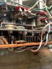
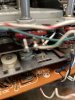
on page 11--where there are "9 screws (all slotted 1-9)"--the diagram looks ot be pointing to the white standoffs--but it seems that the impossible flat brass hex head screws are the ones holding the linkage plate to the switches beneath?
Has anyone been able to remove this? they are too flat and small for me to unfasten.

Thanks for the help.
 

Attachments

  • advent 201_1.jpg
    advent 201_1.jpg
    120.4 KB · Views: 55
  • advent 201_2.jpg
    advent 201_2.jpg
    146 KB · Views: 57
Register to hide this ad
FWIW - when we worked on 201's - we didn't remove the boards. We trouble shot it from the solder side of the PC bards. Commonest problem was failure of one of the TIS-97 transistors. We would unsolder leads, remove the bad transistors (usually with some shaking) and then solder the replacement part (with insulation on the leads if necessary) on the circuit side of the PCB. Actual removal and reinstallation of the board is difficult, and very time consuming. (actually, I never got to remove and install it, although I did repair some with bad transistors - this was 40 or so years ago, so tech beware) Good luck with it.
 
That is very helpful to know.

I believe I still have some 2n5088's--are those a suitable replacement in this application?

Also--am I right to think I could swap the two tape head rca connections at the board to isolate whether the cause of the dead channel is on the board or on the transport?
These rca's and their wiring are pretty delicate and already pretty chewed up.

The output level pot on the side is going out--the good channel needs to be about 70% before any sound comes out--seems like this is another possible culprit of the bad channel but seems weird that it cut out completely. tried cleaning it to no avail.

Thanks.


FWIW - when we worked on 201's - we didn't remove the boards. We trouble shot it from the solder side of the PC bards. Commonest problem was failure of one of the TIS-97 transistors. We would unsolder leads, remove the bad transistors (usually with some shaking) and then solder the replacement part (with insulation on the leads if necessary) on the circuit side of the PCB. Actual removal and reinstallation of the board is difficult, and very time consuming. (actually, I never got to remove and install it, although I did repair some with bad transistors - this was 40 or so years ago, so tech beware) Good luck with it.
 
Confirmed: swapping rca's from tape head to board made no difference in which channel is dead--
will take a look at replacing the output pot that is cutting out and possibly the transistors.

I would love to have full access to the board for a more of a rebuild while I am in there--but I have mangled two of those flat brass hex heads trying to loosen them up; very strange the service manual says they are removable, and are so difficult--a pan head screw would have accomplished the same thing.
 
Still trying to figure out these fasteners—ordered some smaller hex nut drivers to see if they can loosen.

a friend thought they could be press fit spacers, but the stems look threaded through the switch plate on the underside...
 

Attachments

  • 5B3742A8-D1EC-46C8-A466-811886220B68.jpeg
    5B3742A8-D1EC-46C8-A466-811886220B68.jpeg
    113.6 KB · Views: 46
  • 9E009641-1F5F-46DA-865F-7A349C5C5DB2.jpeg
    9E009641-1F5F-46DA-865F-7A349C5C5DB2.jpeg
    102.5 KB · Views: 44
Had a similar problem where I used to work. Hex heads, with very low width. All the sockets have beveled edges, and couldn't get a good bite on the heads. Ended up grinding one flat so no bevel.... YMMV
 
You might also be able to remove the screws with an ignition wrench or a small crescent wrench which may provide better purchase on screws with low profile heads.
 
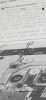
Just got this close up snip from a service manual listing showing slotted screws where they are supposed to be.
 

Attachments

  • E8F04F56-FF6B-4830-829C-063AACB4818F.png
    E8F04F56-FF6B-4830-829C-063AACB4818F.png
    392.1 KB · Views: 31
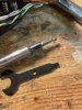
Used a tiny dremel drill bit and my smallest screw extractor. This could be interesting. Stay tuned.
 

Attachments

  • 09407A9A-6611-49DC-AEE6-CF8FDCBD669F.jpeg
    09407A9A-6611-49DC-AEE6-CF8FDCBD669F.jpeg
    157.7 KB · Views: 27
The last time I worked on one I was suppose to modify it as per the service instructions and that did not work at all so I put it back the way it was bit the unit had horrible performance any way you look at it so I would not even take in a another of those- they are like dual cassette decks, I don't work on them.
It looks like you need to unsolder the switch from the board not fool around with those fasteners that were not meant to come out.
 
I seem to have gotten this working.

I drilled out or extracted all of the fasteners.
I replaced the ones I could remove with m3.5 panhead coarse thread machine screws.

I replaced all of the tis97 transistors with 2n5088—the only way I was able to do this is I found a copy of the service manual that came with a massive poster sized foldout pictorial schematic intended to hilight the Dolby circuit—but also provided a legible map of the entire board. Hifi engine doesn’t seem to be accepting uploads but I’d love for this to live somewhere online because it does not appear to be available.

The volume pot was also dying. And was replaced.

I ended up redoing a lot of the wiring—perhaps because the way this was intended to be unfolded to service the connections all get over stressed and brittle.

Not sure with certainty what was ultimately the problem.
 

Attachments

  • image.jpg
    image.jpg
    177.1 KB · Views: 31
  • image.jpg
    image.jpg
    151.8 KB · Views: 29
You have far more patience than I. Not sure I would have dedicated so much time to a 201... probably because I don't have the electronics skill to fix one. These are still nice sounding decks 60 years after they were first introduced. I have the OEM Advent and a very similar unit from Wollensak. Always enjoy getting them into the rotation.
 
Now I’m having some issues that I believe ive narrowed down to the head wiring for one channel—

does anyone have a recommended spec for 2 conductor + shield/ground wire to use as a replacement?
 
I definitely don’t have the skill for this either. Lol.

It’s a friend’s roommate and I was reluctant to take it on because old tape units are so densely packed I find them maddening. Driven by guilt at this point.

You have far more patience than I. Not sure I would have dedicated so much time to a 201... probably because I don't have the electronics skill to fix one. These are still nice sounding decks 60 years after they were first introduced. I have the OEM Advent and a very similar unit from Wollensak. Always enjoy getting them into the rotation.
 
Hi there,

I realize this is an old post but I appreciate the info as I’ve just picked up a 201 with a wonky channel.

Any chance you could snap some closeups of that big board layout diagram you posted? I’m too blind to read the markings when zoomed in.

Thank you!

Jim
 
Trying to find the digital file--I do still have the physical foldout poster sized photo-schematic--which is an amazing resource and should have a place on the internet for posterity as it is invaluable trying to rework that board. If I cant find the digital file ill see if i can rescan it, but have to use the large format scanner....
 
Trying to find the digital file--I do still have the physical foldout poster sized photo-schematic--which is an amazing resource and should have a place on the internet for posterity as it is invaluable trying to rework that board. If I cant find the digital file ill see if i can rescan it, but have to use the large format scanner....
If you find it, it would be nice if it were in the AKdatabase gallery. If they fit, email them to ak.pdfs@gmail.com
 
Trying to find the digital file--I do still have the physical foldout poster sized photo-schematic--which is an amazing resource and should have a place on the internet for posterity as it is invaluable trying to rework that board. If I cant find the digital file ill see if i can rescan it, but have to use the large format scanner....
That’s awesome, thank you!!

I managed to disassemble the beast to the point I have access to the circuit board. I’ve found one dead transistor so far. The board is so densely packed it’s almost impossible to get the transistor tester test leads on some devices!

Jim
 
Was just thinking, even if you good to a series of overlapping photos that covers the whole layout would be super helpful.

Sick in bed today so I didn’t get back to it. Hoping to resume tomorrow.
 
Back
Top Bottom