• The move to the new server is done. There are some software and database maintenance updates in process. This has us passing the hat around to help out. We appreciate any donations. Seriously, even a dollar helps. The payment page may be found here - https://www.audiokarma.org/support.html

Advice on restoring AU-D11/II

This amplifier has balanced outputs. What this means is that there are actually 2 complete amplifiers in each channel, one drives the + speaker output and one drives the - speaker output. This is very important! - speaker outputs are NOT connected to ground! When the amp is correctly working, if you measure between + and - speaker outputs you will have 0VDC and if you measure from + or - speaker outputs to ground you will have 0VDC. There are adjustments for this. If you attempt to perform the adjustments and don't get 0V, Do not connect speakers!
When probing with a meter probe, put electrical tape around the probe tip so only the very tip is exposed. This will help prevent what happened from happening.
Test all the output transistors on the bad channel, then test the drivers. Keep going until you stop finding bad transistors. Then replace the bad ones. Also replace ALL the outputs on that channel because you don't know if any of the others may have been stressed and damaged.
 
When you find replacement transistors, you ought to get some long clip-type test leads for your meter, insulated to the tips. Even then, connect them with power off; once connected, power up, make measurement/adjustment, then power off. It is very easy to short these big output transistors, as you now know.
 
Thanks @dr*audio !
So I unhooked the left speaker and I double checked the adjustments for the right side. The right side sounds great! Now to troubleshoot the left side after my dumb mistake.
 
When you find replacement transistors, you ought to get some long clip-type test leads for your meter, insulated to the tips. Even then, connect them with power off; once connected, power up, make measurement/adjustment, then power off. It is very easy to short these big output transistors, as you now know.
Trust me, I feel awful for how dumb of a mistake I did....
 
Last edited:
Time for a update and some questions!

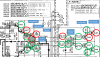
Below is a the area I have found the troubled parts in. To recap what had happened, I dropped my multimeter lead on Q61 and created a short.
The green circles mean all has tested out correctly and the red circles mean parts that did not.

I'd like to make sure I am testing the transistor correctly. So, for a NPN, I'd take my multimeter and put it on the diode setting. Then, I'd leave my positive lead on the Base and my negative lead (one at a time) to the Collector and Emitter. I should see between .4 to .9 volts. And for a PNP, basically switch the polarity of the leads and run the same test. All correct?

I have the corresponding part numbers I ordered below in the picture (ordered from mouser). Do that look all correct? I found all these crosses here within different forums.

I noticed for Q3 and Q7, I will have to have to watch my leads because the new transistors go EBC and on the board, the old ones go ECB. any suggestions? I will also replace Q4 and Q 8 just to be safe.

Last thing, is there any where else I should double check before power up this unit after I install these parts???

AU fix.png
 
Looks about right - in other words what I would expect.

Do you have, or can you build a 'DBT' ? - this is a huge help and stress reliever for that first power-on after major work. ;)
 
Looks about right - in other words what I would expect.

Do you have, or can you build a 'DBT' ? - this is a huge help and stress reliever for that first power-on after major work. ;)

Yes I do! What wattage bulb should I use? I was thinking either 100 or 150.
 
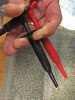
At risk of repeating myself, I strongly recommend you get some long clip-type test leads for your meter, insulated to the tips. Even then, when adjusting the power amp, steps 5 - 8, turn off the power before connecting the clips; once connected, power up, make measurement/adjustment, then power off, then go to the next step. Sounds tedious, but it's the safe way to avoid shorting those big output transistors. I like these Mueller spring-loaded probes, but there are others out there.
Probes.jpg
 
Okay, I replaced q53, 57, 61, 3, 7, 4, 8. Everything checks out to be okay! So, I proceeded to do the DBT. That went well but, the amp never kicked out of safe mode.
I proceeded to see the mV between q61 and q63. I got .63mV. I was about to adjust it till I noticed c52 and r58 where burning hot! I quickly turned off the amp. I know that's not right. I checked the resistors around r58 and everything checks out. The cap checks out to be okay too.
Once again, I'm lost and need some direction. I have yet to look into the power amp board. I got to be close...
 
For driver transistors why would you use mje15032/3 ? You may still get the 2SA1837/2SC4793, or 2SA1930/2SC5171 which are a lot closer to the original parts.

I noticed for Q3 and Q7, I will have to have to watch my leads because the new transistors go EBC and on the board, the old ones go ECB. any suggestions?
The ksc945C is center collector, as well as the KSA733C (ECB pinout) so they are pin compatible with the 2sa1115/2sc2603. Just make sure you get the C suffix parts because the parts without this sufix are EBC. This is stated in the fairchild datasheet.
 
Wondering how it's going. I'm sure you realize that you haven't much choice but to go carefully back through your work looking for the bug. You have a good channel to compare with. Did you replace resistors and trimmers, too? I once did myself in by failing to notice the little "k" on my meter readout. Duh! Took me a while to find that little mistake, but I did, and no serious harm done except a few hours of diagnosis and detective work. Keep after it; you'll find it.
 
Back
Top Bottom