• The move to the new server is done. There are some software and database maintenance updates in process. This has us passing the hat around to help out. We appreciate any donations. Seriously, even a dollar helps. The payment page may be found here - https://www.audiokarma.org/support.html

Advice requested on repair Yamaha CA-1000

jansen2810

Active Member
This is my first post, so I had better introduce myself. I am Duch, 67y old, part-time pensioner, I have some experience with recapping and restoring Yamaha gear (CT-7000 and A560) and other amps, but no pro whatsoever. I would really like some on advice on this one.
I bought this CA-1000 in mint condition (never been worked on, cabinet never been opened besides me), but with issues.

1. Class A does not work at all, no clicks from SP protection
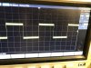
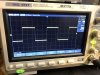
2. Normal does work, but unstable, protection kicks in one and a while, but it comes back. (8 Ohms dummy-
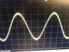
load, on bulb current limiter and variac, both channels same results, see first pictures) Sinus and squares look 'spiky' rough on the edges.
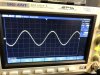
3. Pre-amp works flawless on normal, sounds good on tube power-amp. (see pictures)
4. Pre-amp works almost flawless on class A, sometimes I am losing the negative part of the 1 khz sinus, bulb flickers and is rather bright (high current?)
Everything on BOTH channels.

Did not do anything yet awaiting advice
Intentions:
1. New microswitches N/Class A switch
2. Recap/rebuild power-board. I have bad experiences with Toshiba 2SC458-type (square-looking,black feet)) transistors so I want to replace them.
3. Look what happens after this.

What do you think, advice?
 

Attachments

  • normaal 2.jpg
    normaal 2.jpg
    106.5 KB · Views: 53
  • normaal.jpg
    normaal.jpg
    104.7 KB · Views: 51
  • preamp 1 normaal.jpg
    preamp 1 normaal.jpg
    97 KB · Views: 49
  • preamp 2 normaal.jpg
    preamp 2 normaal.jpg
    105.4 KB · Views: 49
  • preamp class A.jpg
    preamp class A.jpg
    103.8 KB · Views: 49
Register to hide this ad
Main known problem areas.

There are fusible resistors on the power supply.
Fair chance they have drifted high and are causing the main problems.

I think there are some fusible resistors on the input board, I forget, it’s been a while. They are probably bad also.

The micro switches are suspects.

I would go after the fusible resistors first, change to metal film resistors, then check amp adjustments and operation.

New micro switches and a full recap are worthy effort to get it up to glory. Do be aware that the traces on the input board are delicate so good de-soldering skills are advised.
 
Thanks for your reply, Could you explain why the fusible resistors on the input board could effect both channels in the same way, furthermore the preamp works fine. How do I interpret 'input board'. Function circuit board? Rear Panel circuitboard? Operation circuit board?
Thanks for the de-soldering warning! I just treated myself with a HAKKO de-soldering gun. ;-)
 
Could you explain why the fusible resistors on the input board could effect both channels in the same way,
The single power supply for the function board goes through FR401. If that fusible is messed up it will influence both channels.FR402 is for the microphone amplifier.
4. Pre-amp works almost flawless on class A, sometimes I am losing the negative part of the 1 khz sinus, bulb flickers and is rather bright (high current?)
Class A operation has nothing to do with the pre-amp..
 
Last edited:
2. Recap/rebuild power-board.
A prudent idea.Probably cure your intermittent. All of the slide switches will most likely all need to be disassembled and cleaned.Especially the rear panel coupler/decoupler switch.
 
Thanks for your reply, Could you explain why the fusible resistors on the input board could effect both channels in the same way, furthermore the preamp works fine. How do I interpret 'input board'. Function circuit board? Rear Panel circuitboard? Operation circuit board?
Thanks for the de-soldering warning! I just treated myself with a HAKKO de-soldering gun. ;-)


I recommend NOT using the Hakko.
I find they heat poorly and you’ll tend to stay on the trace too long. Then the suction will pull the trace. I’ve experienced that. I find a good solder station (I use and old Weller with a 700 degree tip) and a good eye and a small hand solder sucker work best. Quick, accurate, easy to control.

I am seriously disappointed in the Hakko.
It works great on some gear with unbent pins but on bent pins or delicate traces, it’s junk.


RE: function board, yes, I think of it as controlling what input is selected. It’s the board on the top under the cover in the back. It removes easily with plug in connectors. Be VERY delicate unsoldering on that one. It is tightly populated with parts and has narrow traces that damage easily.
 
+2^^^ as above
Also, fusible resistors on power/relay board underneath F701,2,3,4
Maybe basic health check of power supply, measure dc voltages at either power amp board
pins +50, -50, +B, -B, C. Expect +/-50V or there abouts in Normal except for C at +1.9V
 
Everyone thanks for all the replies! Should there be something I should know......anytime. I just wait for the switches to arrive and than back to work.....!
 
I recommend NOT using the Hakko.
I find they heat poorly and you’ll tend to stay on the trace too long. Then the suction will pull the trace. I’ve experienced that. I find a good solder station (I use and old Weller with a 700 degree tip) and a good eye and a small hand solder sucker work best. Quick, accurate, easy to control.

I am seriously disappointed in the Hakko.
It works great on some gear with unbent pins but on bent pins or delicate traces, it’s junk.

RE: Disappointing to hear, I was so proud to be able to buy one. They are hardly to obtain in the Netherlands (220V !!). But as we say over here, a warned man counts for two! Until now I used a hand sucker and sometimes litzewire (I am not good in using it). Bent pins are a nuisance, I know. I hoped the HAKKO would help.


RE: function board, yes, I think of it as controlling what input is selected. It’s the board on the top under the cover in the back. It removes easily with plug in connectors. Be VERY delicate unsoldering on that one. It is tightly populated with parts and has narrow traces that damage easily.

RE: Disappointing to hear, I was so proud to be able to buy one. They are hardly to obtain in the Netherlands (220V !!). But as we say over here, a warned man counts for two! Until now I used a hand sucker and sometimes litzewire (I am not good in using it). Bent pins are a nuisance, I know. I hoped the HAKKO would help.
 
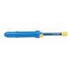
I use a Sodapulit 99% of the time.Very proficient..:thumbsup: I think I'm on my 3rd one.Maybe 4th..I wear them out..:biggrin:

View attachment 1638430

I have the same one only metal. Rather small, you can operate the spring with one hand. I have also a bigger one, I tighten the spring against my chest. I don't like these handsuckers, because they have some kind of recoil and that can also damage the tracks. Using the sucker twice on the same pin is a no go, you have to apply solder again and try again. Pins that are bent stay sticky. I use a sharp little knife to get them straight while heating the pin.
 
At the risk of looking stupid, I am still gone ask this. Studying the schematics of this amp I see two different power rails from different windings of the transformer. One goes to the powerboard gets rectified and stabilized. 50+ en 50-, the other one goes through the class A/Normal (C,A and S/B) again different windings, rectified, buffered (big caps) to mainboard. Somehow they all merge together. B+ en B- and the 48+ and 48- (normal) at the main amp board. How does this work? I really like to grasp what's going on there and is going wrong and why? Of course I could start replacing components, but honestly I like to know what I am doing.
 
At the risk of looking stupid, I am still gone ask this. Studying the schematics of this amp I see two different power rails from different windings of the transformer. One goes to the powerboard gets rectified and stabilized. 50+ en 50-, the other one goes through the class A/Normal (C,A and S/B) again different windings, rectified, buffered (big caps) to mainboard. Somehow they all merge together. B+ en B- and the 48+ and 48- (normal) at the main amp board. How does this work? I really like to grasp what's going on there and is going wrong and why? Of course I could start replacing components, but honestly I like to know what I am doing.
The two snap action switches that straddle the class A/Normal switch determine which unregulated voltage rail is selected...Class A operation requires a lower rail voltage than the normal mode. The snap action switches just determine which secondaries off the transformer is selected.
Class A rails +/- 18vdc
Normal rails +/- 48vdc
 
Last edited:
I recommend NOT using the Hakko.
I find they heat poorly and you’ll tend to stay on the trace too long. Then the suction will pull the trace. I’ve experienced that. I find a good solder station (I use and old Weller with a 700 degree tip) and a good eye and a small hand solder sucker work best. Quick, accurate, easy to control.

I am seriously disappointed in the Hakko.
It works great on some gear with unbent pins but on bent pins or delicate traces, it’s junk.


RE: function board, yes, I think of it as controlling what input is selected. It’s the board on the top under the cover in the back. It removes easily with plug in connectors. Be VERY delicate unsoldering on that one. It is tightly populated with parts and has narrow traces that damage easily.


Why? I use it exclusively on all my repairs for over 4 years now and never had it pull a trace up or take to long to heat the solder. I actually use it some times to add solder on large GND planes when my regular iron just can't cut it. I think my model is the 808 .

nashou
 
Last edited:
Back
Top Bottom