• The move to the new server is done. There are some software and database maintenance updates in process. This has us passing the hat around to help out. We appreciate any donations. Seriously, even a dollar helps. The payment page may be found here - https://www.audiokarma.org/support.html

Aiwa FX-W86 Proprietary Connector

MJ74

New Member
Hi

I'm thinking of buying an Aiwa FX-W86 cassette deck as I had one in the 90s and really liked it. However, this model has a ribbon cable and proprietary connector on the back.

Does anybody know if it's possible to replace the ribbon cable with RCA plugs and cables? I've done some Googling but can't seem to find much useful info.

Thanks
 
Register to hide this ad
Likely your first issue will be the operating voltage. It was not uncommon for units like this to use low voltage AC in the 16 to 20 volt range (sometimes DC). This was partly due to the limitation of supplying AC mains voltage through a ribbon cable, not that it is not done at times and the fact that the main unit could have a power supply that could be used for the rest of the units.

I took a quick look on the net and did not see a free manual and the picture of the rear that I found does not show an AC mains power cord.

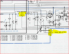
Below is part of the schematic for a similar deck/same brand. Note that the input directly feeds a 12 volt regulator. It is not likely that it is AC mains voltage.

upload_2017-8-7_13-11-18.png

The unit that you are looking at could be different. You will need to do more research.
 
The schematics for the unit are really what you need to determine what changes need to be made to operate the unit with power being supplied from a source other than the one to which it would normally connect and with the inputs and outputs connected through RCA interconnect cables to an external receiver/amplifier. If the power supply configuration is similar to the one shown in I LIKE MUSIC’s post, the voltage rating of the capacitor(s) connected to the output of the bridge rectifier (D1 in this case) would allow you to calculate the AC voltage needed to operate the unit. The schematics would also show you where the input and output signals connect to the internal audio circuits. With this information you could install AC power and RCA jacks on the rear panel, wire them to the correct internal connection points, connect the unit to the external receiver/amplifier and connect an appropriate AC power adapter (a.k.a. wall wart) to power the unit.

Another approach you could take, assuming you can obtain the schematics and a mating connector for the one attached to the end of the ribbon cable, is to build a small breakout box that would contain the AC power adapter and termination strips for the AC power and the audio connections so these can be converted to RCA cable type. This would allow you to avoid opening up and modifying the internal connections of the cassette recorder. You could instead connect the cable coming out of the cassette recorder to the box and then connect the RCA cables to your receiver/amplifier.
 
Last edited:
Thanks for the advice both. I'll do some more research before buying. I like the idea of building a breakout box..
 
Back
Top Bottom