• The move to the new server is done. There are some software and database maintenance updates in process. This has us passing the hat around to help out. We appreciate any donations. Seriously, even a dollar helps. The payment page may be found here - https://www.audiokarma.org/support.html

Akai AA-1040 receiver - No left channel

Homer4beer

Well-Known Member
Hi guys,

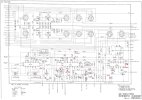
I've spent considerable time so far trying to work out this problem before posting here. Using an oscilloscope I've traced the signal loss through to the MFC PC Board on the amp. When tracing the signal off this board there is a right signal but no left signal.

Numbers 21, 22, 23 and 24 on the diagram go to the tone control board which them goes to the Filter PC board and then on to the Main amp board. There is signal from 21 (R Chan output) all the way to the main output board (hence having sound) but nothing from 23 (L Chan output).

So having traced the signal loss back to the MFC PC Board I'm having difficulty working out where the signal is now coming from with all the SW switches. I find these very confusing. The amp is going to be quite difficult to work on also with the tuner module as part of the same board.

Can anyone suggest where to go from here? I've tested the R92 resistor which is fine but now I'm stumped.

Thanks guys :)

XIw0C0.png
 
Register to hide this ad
As a test, you can feed the "Tape out: connections to the "Tape in" or Aux connections on another unit. Tape out should be the same level as pin 23 left and 21 right. If you only get 1 channel to work (R), try cleaning those rotary switches well with deoxit. If that doesn't work put the unit in mono to see if sound comes out of the left speaker. If so you may have either very dirty, or a bad rotory switch contact, or possible bad connections, or a crack on that circuit board. Look for cracks where screws hold the board, or where somethin heavy like the tuning capacitor may be mounted.
 
Thanks Tom. After putting the resistor back in I did lots of circuit tracing with a multimeter checking continuity and . I'm not sure what I did (resoldering the resistor, moving the rotary switch multiple times, pushing a contact on the rotary switches, inadvertently moving a wire back into place, closing a short circuit through pressure on the board?) but it now works perfectly again.

Bizzare!
 
Hi guys,

I've spent considerable time so far trying to work out this problem before posting here. Using an oscilloscope I've traced the signal loss through to the MFC PC Board on the amp. When tracing the signal off this board there is a right signal but no left signal.

Numbers 21, 22, 23 and 24 on the diagram go to the tone control board which them goes to the Filter PC board and then on to the Main amp board. There is signal from 21 (R Chan output) all the way to the main output board (hence having sound) but nothing from 23 (L Chan output).

So having traced the signal loss back to the MFC PC Board I'm having difficulty working out where the signal is now coming from with all the SW switches. I find these very confusing. The amp is going to be quite difficult to work on also with the tuner module as part of the same board.

Can anyone suggest where to go from here? I've tested the R92 resistor which is fine but now I'm stumped.

Thanks guys :)

XIw0C0.png

@Homer4beer: Hi, this is my first post although I have been reading many of the posts with interest. Anyway, I have a similar issue except it's the Right channel, and am finding the MFC board a puzzle same as you did. I know you sorted your problem, and that this is an old post, but my query is regarding the Service Manual. The one on this forum, and everywhere else it seems, only has the odd-numbered pages. The MFC board layout is on an even numbered page (I guess), and I cannot work out which terminal pins (the wire wrapped ones), are which. It was a while ago, but just wondering if you can recall if you had more info. Regards, H.
 
Many thanks for this; very kind of you to take the trouble. Now the fun begins. I have a feeling I will need to be under the tuning gang. I just hope I don't need to re-thread the dial cord. Regards.
 
@Ylli: Thanks to your help and a very good SM, I was able to fix the problem. I'm including a few notes which may be of assistance to others. To trace the fault I injected a 1kHz signal in pcbs starting with the Main Amp board (pins 2 and 4). Apart from the MFC board, the AA-1040 is easy to work on. The wire-wrap terminal posts on the pcbs seem to have all the input and output signals. Observing good signals from both speakers, I moved on to the Filter Mute board (pins 5 and 7); both channels OK here as well. However, when I applied the 1kHz tone at the Tone Control board (pins 3 and 1), the Left channel was missing. Consulting the SM, I checked the voltages on the board's transistors, and concluded that TR1b was defective. I noted it was a 2SC458, and that forum members had posted some very useful info about this 'notorious' transistor. I replaced it with a 2SC1845, which has the same pinout/package orientation as the 2SC248, (bearing in mind that the Ic max is only half of the 2SC458). To gain access to the component side of the Tone Control board, I had to remove the front panel, and then the bracing plate attached between the front panel and the chassis. While I was in there, I replaced the other 2SC248 (for the Left channel). I've had it up and running for a few days now with no problems. I couldn't have done it without this forum. Thanks.
 
Back
Top Bottom