• The move to the new server is done. There are some software and database maintenance updates in process. This has us passing the hat around to help out. We appreciate any donations. Seriously, even a dollar helps. The payment page may be found here - https://www.audiokarma.org/support.html

Akai AA-1135 No Relay Click

smovlov

New Member
Hi All,

Been reading on this forum for a while and am thankful for all the information that's been put out over the years.

I'm writing now because I have a receiver that is not currently working and I need some assistance on how to repair it.

The receiver worked for about a year or so when suddenly it would click off at the relay. I could turn it off and back on and it would work. Later it started to click repeatedly on and off every two seconds, finally shutting off and unable to be restarted. Now, it stays off and wont turn back on.

I turned it off and unplugged it for a week or so and it worked for about 3 hours, clicking off after a and now wont work again.

I'm at a bit of a loss at where to start. When I turn the unit on, the lights come on and the needles move but no relay clicks.

My guess is something is up with the power board but I don't know how to start testing that. I do know how to use a multimeter and I have a basic understanding of electronics. Any advice or suggestions are greatly appreciated.

Thanks all,
Christian
 
Register to hide this ad
Firstly, download the service manual, freely available on hifiengine, need to register, safe, no spam.
https://www.hifiengine.com/manual_library/akai/aa-1135.shtml

Reads like you have intermittent component failure causing some dc voltage to be dumped on the speaker line.
The amps protection circuit detects this Vdc and doesn't activate the relay, thereby protecting the speakers.
Will try and find some test points.

Welcome to AK, plenty of people to help you out.
 
Two possible scenarios, either excessive dc voltage on speaker line or failure of the protection circuit. From symptoms
most likely excessive Vdc.

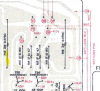
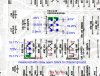
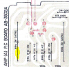
When the problem occurs, measure the dc voltage at the emitter (large white ceramic) resistor leg as shown, black probe
connected to chassis/ground or black speaker post. Right channel.
upload_2021-7-13_12-20-31.png

Repeat for other/left channel
upload_2021-7-13_12-21-45.png

Typically less than 50mV, 0mV is ideal. Anywhere above a few hundred (3-4) will probably trip protection.
 
Thanks for the warm welcome mbz!

I've got the receiver on now and am playing a few records. I measured the power at both resistors: the right was around 5mV and the left at 2mV. I'll report back once the protection relay kicks in.

Not sure its related but in the past I've had to bump the volume up in order to get the left channel to match the right. Could that be related to the power issue or is that something else? The left channel volume is lower then the right, turning the volume up seems to clear something and balances the volume output.

Thanks again!
Christian
 
Listened to 3 LPs before the protection relay opened up. Measured the voltages at the same locations: 4mV for the right and 2-3mV for the left. Basically the same as when the relay was closed right?

I have a few ideas but would like to hear your thoughts.

Christian
 
DC offset of 2-5mV is great, no issue there.

If the subsequent measurement of 4mV and 2-3mV was with the relay still open then that would point to a problem with the protection
circuit, ie, the measurement needed to be made while the relay is still open, ie, no audio output. Will try and find another schematic,
the hfe manual is not great.
 
Manual from AK database (1135L) is reasonable.
Probably an issue with sagging voltage to the protection circuit. C15 is used for the power on mute timing, however if it becomes
somewhat leaky then the relay may drop out controlled by TR14b voltage. Could also be tired silicon. At power on, if the time to
relay click is consistently about 4-5 seconds the C15 is probably ok. Replace if time has drifted to 6-10sec...

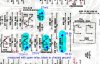
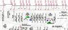
When relay is open (no audio) measure dc voltages at red crosses (black probe connected to chassis/GND
upload_2021-7-13_20-31-1.png
 
From what I remember, the relay click is closer to 5 sec than 10. Ill keep timing it to see what it is.

No click this morning when powering on. Measured the following DC voltages

TR14b: 27mV
TR13b: 765mV
D4: 35.8V both sides
C15: 27mV

View media item 25751
 

Attachments

  • Screenshot 2021-07-13 112910.jpg
    Screenshot 2021-07-13 112910.jpg
    143.2 KB · Views: 19
  • Like
Reactions: mbz
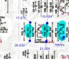
TR13b is too high. TR10 is suspect. TR9 is not suspect since
2-5mV dc offset. D3 is considered unlikely. Measure TR10b and
then e dc voltages to GND. Measure at R27, R28 don't probe
transistor legs.
 
Voltages were variable at each location so I wrote down the range. Again, all measurements were taken with the relay open and black to chassis ground.

When you say "measure at R27" does that mean measure across the resistor? Just so I understand, what is the reasoning vs testing at the leg of the transistor?
 

Attachments

  • Screenshot 2021-07-13 140635.jpg
    Screenshot 2021-07-13 140635.jpg
    156.2 KB · Views: 13
Probing TO-92 transistors is a bit risky, one slip... Prefer to probe another
component connected to same node, eg, safer to probe D3 anode or R27 rather than TR10b.

Requested measurements were to be at node R27/TR10b then R28/TR10e node both with
black probe connected to chassis/GND

The R27, R28 voltage swings are too large, possibly due to intermittent behaviour/failure.
TR10 Vb(R27 17-21V) > Ve(R28 15-19V) so possibly TR10c-e is breaking down. Also of interest
are TR11 and TR12. You could try diode testing (6 combinations) these transistors (amp
powered off) but they will probably pass. Carefully measure b/c/e voltages to GND for these
3 transistors.
 
Thanks for clarifying. Tonight I made a small angled probe with a pointed tip. I added some heat shrink around the end to prevent any potential to short between the legs. I'm probing the underside of the board at the cut end of the leads which is working well.

I'll diode test the TR10 TR11 and TR12 and report back.

See attached for measured DC voltage.
Screenshot 2021-07-14 223214.jpg
Thanks again!
Christian
 
TR11,12 look ok. The voltage swings are still a concern. TR10 is prime candidate, you voltages suggest the e-b junction
is breaking down. You could try measuring Vdc with red probe on emitter and black probe on base, expect steady 600mV (or so)
 
Just measured TR10 e-b junction: 580mV

I tested TR10, 11, and 12 in diode mode. +b -e, +e -b, +b -c, +c -b. TR11 was .611 +b -e, 1.760 -b +e. TR10 and TR12 were between .615 and .658 with the opposites being open.

Not sure if that makes sense, Its late here but I can diagram it out if you feel there's more to unpack.

Thanks for all the help!
Christian
 
TR10 e-b junction: 580mV
Agree, looks good. This is something of a setback. The unstable voltages suggests something is failing intermittent.
Taking a step back, candidates are TR10 eb looks ok, need to look at past posts for e-c. D3 would be a long shot, monitor
voltage red probe anode, black cathode, expect 600mV again. C10 breaking down? (very remote). Appears to be two TR9's
(L&R channel) expect ok since low dc offset. Need some thinking music...

Nice graphic from markthefixer showing expected results from diode test, red/black indicate meter probe
orientation.
DiodeTest.JPG
 
Thanks for sending the diagram!

I measured TR10, 11, and 12 using the methodology in the diagram. Unit off, probes directly to legs of transistors.

TR10 +c -e reads 1.540. Is this because the transistor is in the circuit?

TR11 +e -b consistently showed a reading of 1.800 for a second then went to OL.

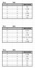
All of the readings for the diode test of transistors are in the attached spreadsheet. All readings were above .650.

I probed D3 +anode and -cathode with the unit on relay open and it was erratic. It would hold 340mV for a few seconds then would go sometimes negative. Never read higher than 350mV. Just tested it again and was extremely variable going from -500mV to 20mV never settling on any specific reading.

Diode test for D3:
+anode -cathode: .670
-anode +cathode: OL
 

Attachments

  • Screenshot 2021-07-15 121728.jpg
    Screenshot 2021-07-15 121728.jpg
    56.5 KB · Views: 12
  • Like
Reactions: mbz
TR10 +c -e reads 1.540. Is this because the transistor is in the circuit?
Yes, alternate path from c- R33(75k)-R28(220)-e

TR11 +e -b consistently showed a reading of 1.800 for a second then went to OL.
Maybe another incircuit issue, I would have thought path through R35 would give a constant reading, maybe charging up C17, 18...

I probed D3 +anode and -cathode with the unit on relay open and it was erratic. It would hold 340mV for a few seconds then would go sometimes negative. Never read higher than 350mV. Just tested it again and was extremely variable going from -500mV to 20mV never settling on any specific reading.
I'm thinking that under normal operation there should be no current flow through D3 since the TR9 transistors are off and no significant
leakage through C10. Problem appears to be downstream D3 (cathode side). You could try lifting one leg of D3 and check for normal
relay operation. Likewise you could lift one leg of C10, appears to be a noise path. The base voltages on the 2 TR9 transistors should be
rock solid, a few 2-5mV from past measurements.

EDIT: Lifting a leg of D3 disables part of the protection circuit so don't connect speakers
 
Last edited:
You could try lifting one leg of D3 and check for normal
relay operation. Likewise you could lift one leg of C10, appears to be a noise path.

What's the best way to lift the component leg? Seems like removing the board from the chassis would allow for the the best access. If that's the case, do I need to discharge the big capacitors before beginning to disconnect the board? Is there a simple way to discharge the unit?

Sounds like I can lift C10 or D3 to achieve the same effect? Removing one of these components from the circuit should allow the relay to close? Testing b of TR9 and TR9B with negative to ground should match which value?

EDIT: Lifting a leg of D3 disables part of the protection circuit so don't connect speakers
Thanks for the note. Ill disconnect the speakers. :)

Christian
 

Attachments

  • Screenshot 2021-07-16 110515.jpg
    Screenshot 2021-07-16 110515.jpg
    96.8 KB · Views: 8
What's the best way to lift the component leg? Seems like removing the board from the chassis would allow for the the best access.
Normally simply unsolder one leg then lift leg out of board, however in real life it looks like you need to remove the vertical power amp board
then unsolder etc then reassemble, yeah a PITA. If you are going to do this work then you might as well replace the part(s). Prime
candidate is D3 sine the voltage drop (Vf) was swinging between 600mV(or so) to near short. Consider replacing, 1N4148 is readily
available, OEM listed as 1S2472.

do I need to discharge the big capacitors before beginning to disconnect the board?
Most units do have resistors to GND that will blead the main caps, others don't. Certainly measure Vdc across terminals of each
main cap, expect mV at most, othewise use a 300-1000ohm resistors across the cap terminals.

Sounds like I can lift C10 or D3 to achieve the same effect? Removing one of these components from the circuit should allow the relay to close?
Looking at the schematic, voltages at R27, 28 are bounching around due to current surges. The destination for this current apears
to be through D3 since Vf is erratic. At D3 cathode the current can either go to TR9 collectors or to C10 then GND if C10 leaky.
Lifting D3 disconnects downstream C10, if relay click suggests problem is either D3 or C10. If relay clicks when lifting C10 then
problem is C10.

I'd replace D3 as a punt/save time...
 
I repaired one of these units recently that had a blown channel. You can unscrew the heat sink from the chassis and then unscrew the amp board from the heat sink without too much hassle. My unit had enough room to get to the solder side once everything was unhooked. It looks much worse than it actually is. The outputs are mounted to the heat sink and then soldered to a smaller pcb board that connects to the main amp board with wires. Some of the power supply regulators are also mounted to the heat sink the same way as the outputs. You should not need to disrupt this small output pcb board to do your work on the amp board.

Definetly discharge the main caps because they are right there in your way. I’d have a look at the solder pad connections throughout the amp board. I think I ended up reflowing them all on my board as many seemed light on solder. I also removed some nasty glue from some capacitors on the amp board. I got lucky and didn’t have any corrosion damage from the glue but something else good to check for.

edit: looking back at my notes, I replaced several fuse resistors on that board. Make sure to measure those as they may have drifted off with time.
 
Last edited:
Back
Top Bottom