• Please note that Audiokarma will be offline briefly for updates early on Monday morning, September 28th.

Akai AA-1135 No Relay Click

So I need to order parts online. We had a great electronic supply store here in Berkeley for 60 years (Al Lashers interview) but they closed recently. There's a few places south in the San Francisco Bay Area but I haven't had the time to check them out.

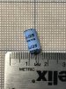
Since I'm placing an order, are there any other components I should pick up while I'm at it? Ill be getting a 1k ohm ceramic resistor to drain the big capacitors and a 1N4148 diode. I have read on other posts that the blue Sayno capacitators are notoriously prone to failure, any sense in replacing these on the board while its out?

You can unscrew the heat sink from the chassis and then unscrew the amp board from the heat sink without too much hassle. My unit had enough room to get to the solder side once everything was unhooked. It looks much worse than it actually is.

I noticed this as well, thanks for the tip!

The big caps are reading about 28V-30V, Ill discharge them before pulling the board out.

The solider pads look pretty good from my view, a few might be on the thin side but most look fine. Ill have a better look when I pull the board out.

looking back at my notes, I replaced several fuse resistors on that board. Make sure to measure those as they may have drifted off with time.

Are these fuse resistors represented by a different symbol than regular resistors?

On another note, the unit has been playing lately without engaging the protection relay ¯\_(ツ)_/¯. Is there anything that I can test while the unit is functioning correctly to help isolate the problem?

Thanks again all!
Christian
 
You should build a dim bulb tester if you do not already have one. Its also standard advice here at AK that you find the fault and fix it first before you begin replacing parts. Since your unit sometimes works and sometimes does not work finding the fault might be a little extra work. Its likely that you may have a bad solder joint somewhere on that amp board. That board has a lot going on with the amp, protection, protection relay, most of the power supply all packed on it. One thing to try would be to tap on the board with a wooden chop stick while the unit is working to see if you can make the issue occur. If you have a failing solder joint you might be able to find it with the chop stick.

Once you find the fault and are able to fix it then go ahead and replace those capacitors that you mentioned. Wouldn't be a bad idea to get some new variable resistors to replace the bias trimmers as well.


From my notes these are the resistors that I replaced in my unit:

R14: 4.7 ohm/.25W
R14B: 4.7 ohm/.25W
R15: 150 ohm/.25W
R15B: 150 ohm/.25W
R16: 150 ohm/.25W
R16B: 150 ohm/.25W
R17: 4.7 ohm/.25W
R17B: 4.7 ohm/.25W
R24: 10 ohm/.5W
R25: 10 ohm/.5W
R31: 10 ohm/.5W
R32: 10 ohm/.5W
R55: 27 ohm/.25W

I believe the schematic or the parts list will have a (F) in notes. You will see that these resistors look different than the rest of the resistors on the board. You should be able to measure these without removing them just to see if they are inline with one another. If in doubt you may need to lift one leg to get the actual reading.
 
  • Like
Reactions: mbz
Hi All,

Time for an update. My parts came in the mail the other day but the receiver has been working normally for the last two weeks. Should I go ahead and replace the diode or let it run until the protection circuit begins clicking again?

You should build a dim bulb tester if you do not already have one.
Ill be putting together something soon.

One thing to try would be to tap on the board with a wooden chop stick while the unit is working to see if you can make the issue occur. If you have a failing solder joint you might be able to find it with the chop stick.
I've tapped around on the board and the relay before to no effect.

From my notes these are the resistors that I replaced in my unit:
Thanks for the list! This will be helpful if I start down that path. Did you have a clean schematic to work from or did you derive the values from the board itself?

I picked up a solder sucker and some de-soldering braid to begin work on the board. I feel like its not a matter of if but when it starts acting up again. I'll assemble a dim bulb tester to test the unit after working on it as well.

Thanks again all,
Christian
 
`One other direction suggestion. Make sure all ground connections are secure. Many receivers use a single ground connection through one of the PC board mounting screws - if that is the case and it is loose, it can cause intermittent relay issues. Look for screws connected to PC traces - on the amp board or the input connection area. if problem reoccurs, try tightening those screws to see if problem goes away. Or, alternatively, loosen some to see if problem gets worse....
Also, sometimes there are long traces with cracks in them. These can cause screwy intermittents, and are very hard to find, unless problem is on all the time... My 2 cents.
 
  • Like
Reactions: mbz
Happy New Year everyone. I have some updates.

(TL;DR Left the unit on for a week while on vacation and the relay wont click, back to troubleshooting. Proceed to **)

After my last post the receiver stopped flipping the relay. Since it was working so well, I held off tearing it apart and replacing the diode as I wouldnt be sure that would be the cure. Well last month I left the receiver on for a bit and I came back to find the protection relay flipping on and off at about a one second interval.

Fast forward a month or so to now. My wife and I went on vacation to see family for christmas and when we got home I saw that the receiver was ON! :( Not sure what happened while we were gone but I haven't gotten a relay click out of it since. There are no obvious burns or damaged caps in the unit.
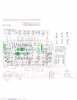
**Heres what I've done to begin troubleshooting
  • Measured voltage at the same locations as before and marked the readings on the attached image.
  • Lifted the leg of D3 and tested the unit on a dim bulb tester 60w bulb (DBT). No relay click. Forward measured .660, reverse open.
  • Soldered D3 back in and lifted the leg of C10. Tested unit on DBT, no relay click. NOTE: I did not replace D3 it as it seems to be good.
  • Examined the underside of the amp board for any loose connections. Everything seems good.
  • Checked ground screws, all were tight.
At this point I think I should go back and meter test TR10. One thing to note is that the voltages at TR10 were variable before (15-17 V) whereas this time they were very consistent at 15ish V b and e.

Is it possible that D3 could be at fault, even though the bias measurements are ok?

Open to any and all suggestions on where to go next.
Thanks all!
Christian
 

Attachments

  • 220108_AA1135 - Test.jpg
    220108_AA1135 - Test.jpg
    81.2 KB · Views: 16
Sorry, attachment is unreadable (pixilated)

Been a while, trying to come up to speed...a refresh

Looks like the protect circuit does basic DC voltage detection TR11,12
and over current detection TR9,,,

Previous posts show 765mV at TR13b, causing relay drive TR14b to turn off.

Some swing in voltages around TR10
TR10e...15-19V
TR10b...17-21V
R26/27/28 node 20-23V

Suggests either TR11,12 are dragging down these voltages.
TR11b 2mV, e 0.4mV, c 18-20V
TR12b 0.4mV, e 2.9mV, c 18-20mV
TR10b 15-17V, e 15-17V, c 770mV
TR11,12 look ok

Explore leakage through D3 and maybe C10 also need to rule out R9
 
Hey mbz,
Ive attached the file with better resolution.

I unsoldered D3 and diode check. 660 foward and OL reverse. Tried to power the unnit up with D3 lifted and got no click.

Reattached D3 and unsoldered C10. again, no click

Could D3 be bad even though it checks out? I have a new one on hand and could replace.
Ill check R9 and see what it reads.

Thanks!
 

Attachments

  • 220108_AA1135 - Test.jpg
    220108_AA1135 - Test.jpg
    124 KB · Views: 12
  • Like
Reactions: mbz
Tried to power the unnit up with D3 lifted and got no click.
This should rule out D3, TR9 and C10. Not much left but TR11, 12. Will have a look at latest file.

EDIT:
The grey wires in the transformer secondarys (Fuse F2, pin 18) provide a
negative supply to TR13b via R44(24k), D5(half wave rectifier) and R34(5.6k?).
Maybe this supply is sagging/leaking a little. In circuit measure R44 and
R34 (amp powered off). Inspect C16 22uf/25V, replace if spare handy
 
Last edited:
Thanks mbz,

I lifted R44 and R34. R44 was spot on but R35 was a little low, anolog meter showed about 5k (min should be 5.3k). Is this a concern?

C16 is a blue Sanyo caps which are apparently problematc. Should I replace with a film cap? The only 2.2uF film cap I found is KEMET R82 50V 2.2uF.

Since the Sanyo caps are known to cause trouble, Im planning to pick up replacements for C1 and C1b. I wont be replacing these until after the unit is back to working again.

Been reading a lot and still so much to learn. Thanks for all the help!
Christian
 
Just checked TR11 and TR12 in the circut, unit off. Would they read different if they were removed from the board?
 

Attachments

  • 220111_AKAI - TR11 TR12 Check.jpg
    220111_AKAI - TR11 TR12 Check.jpg
    63.1 KB · Views: 6
R34 should be 5.6k, for the cost of a few cents I'd replace. It wont be the cause of your problem.

Surprised that C16 is 2.2uf, it looks like performing a storage/filtering role for the half wave rectified voltage so more
likely to be 22uf??? I don't know how the kemet would stand up to the ripple, nothing in the specs, I'd try for a basic
electrolytic, Nichicon UPW would be nice but anything would do. If you had a 47uf/50v...100v or 100uf/50v...100v
then those would do.

In transistor circuit testing can be tricky, the multimeter current may flow through alternate paths, probably why TR11e-c
shows 0.735, if in doubt then need to be removed from the board.
 
Pulled TR11 and TR12 to bench test. Both checked out. Values we not much different. TR11 e-c is OL.

, Nichicon UPW would be nice but anything would do.

Noted, I'll see what I can find.

Nichicon UPW would be nice but anything would do. If you had a 47uf/50v...100v or 100uf/50v...100v
then those would do.

Are you saying replace C16 with a 47uf or replacing C1/b with 47uf?

What liteature are you using to trace the signal path? Ive been using the board schematic to find compoets but I dont have a good schematic to refrence.

Thanks!
Christian
 

Attachments

  • Sanyo 2-2 25.jpg
    Sanyo 2-2 25.jpg
    146.8 KB · Views: 8
Last edited:
Agree the free service manuals are not real clear, I'm using the schematic from the AA-1135L.
It does appear to be C16, currently 2.2uf/16V that can be bumped up to whatever electrolytic you have handy in 50V or better.
It appears to be for storage/filtering of that half wave rectified voltage.
upload_2022-1-12_19-9-12.png

upload_2022-1-12_19-10-20.png

I had a look at the parts list, C16 listed as a solid aluminium, they generally have lower ESR and higher ripple handling.
So yeah, ok to replace with a wet (ordinary) type, 47uf-100uf 50-100V
 
Update. Capacitor and resistor came in today. I replaced C16 with a 47uF 50v, hooked up to the dim bulb tester, unit powered on and the relay clicked in about 3-4 seconds. Cycled the power on and off a few times and the speaker protection clicked every time.

So what next? Should I go back and test voltages at TR11 and 12?

Thanks again for all the help,
Christian
 
Update. Capacitor and resistor came in today. I replaced C16 with a 47uF 50v, hooked up to the dim bulb tester, unit powered on and the relay clicked in about 3-4 seconds. Cycled the power on and off a few times and the speaker protection clicked every time.

Just to be clear.. at power up, there is a mute period of 3-8seconds, the speakers are then connected after this time, so expect to hear a click after 3-8 seconds. Thought your problem is that the relay would then cycle sometime after this. Need to go through the history to work out next step.
 
Thought your problem is that the relay would then cycle sometime after this.

Yes, that was my original issue. After a while, the unit would turn on but the relay would not kick on.

The relay clicking on after replacing C16 is a step in the right direction. I have not connected speakers back up to be sure that it has audio. I did measure DC offset and got about 25mV each channel.
 
25mV dc offset is reasonable, 0mV is ideal. Maybe test for audio using cheap headphones? Leave the amp on for a few hours to check for stability/relay cycling...
 
Back
Top Bottom