• The move to the new server is done. There are some software and database maintenance updates in process. This has us passing the hat around to help out. We appreciate any donations. Seriously, even a dollar helps. The payment page may be found here - https://www.audiokarma.org/support.html

Akai AA-R21L restoration

Haverholm

Well-Known Member
So, I bought me a CD player to supplement what has rapidly become my vinyl addiction. That unit is still in transit, but to prepare for its arrival my wife and I turned our basement storage upside down to dig out our old CD collections.

In the process, and deep in an old moving carton, I came upon an old friend I thought long since lost: my very first amplifier that I bought when I first moved out from my parents'.

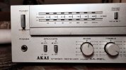
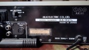
I say "amplifier" because that's all I used it for, but it's really a receiver, an Akai model from 1980-81. I've had it for 30 years, and at least half of that time it's been collecting dust in that cardboard box.

Having had some success with small repairs to my vintage amp, I've decided to try and restore Old Faithful to her former glory. Emphasis on "try", because it will also be a learning opportunity for me as a late tinkering bloomer.

Before I share photos of its current state, I need to ask for your expert knowledge on the model: I've only been able to find info about the AA-R21 (HiFi Engine), but mine is an AA-R21L.

Does anybody know what the L signifies, and if the difference is small enough that I will be able to use the AA-R21 service manual as a guide in this project?

Anyway, pictures or it didn't happen:
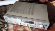
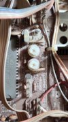
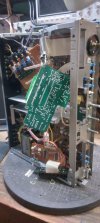
IMG_20251201_182448.jpgIMG_20251201_185938.jpgIMG_20251201_190005.jpgIMG_20251201_190044.jpgIMG_20251201_183541.jpgIMG_20251201_195931.jpgIMG_20251201_195956.jpg

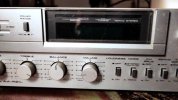
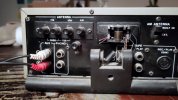
So, it's dirty and the front has a few surface scratches, but I think that's manageable. The big issue here is that the built-in antenna snapped off at some point, and only hangs on by a few wires. I just yanked it off entirely, because that'll require a new part anyway.

But I powered it up with a mobile phone connected to the AUX input, plus a pair of headphones in the front jack — and it plays! Loads of crackle and dropoff because the pots are dirty and settled, but that's small fry.

The real horror story starts where I pop the lid of the receiver. Dropping that in a follow-up so the individual post doesn't take forever to load...
 
Register to hide this ad
Maybe I shouldn't have been so quick to power this fire trap up?

IMG_20251201_191154.jpg
IMG_20251201_195736.jpg
IMG_20251201_195805.jpg
IMG_20251201_195851.jpg

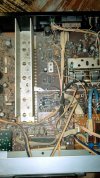
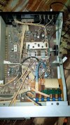
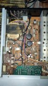
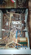
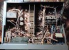
I mean, look at this. It's like Narnia, but instead of eternal winter it's dust bunnies:

IMG_20251201_191249.jpg
IMG_20251201_191319.jpg

It was 8PM when I opened it up and took stock of the insides, and I immediately put off the cleaning job for tomorrow...! On the bright side though:

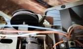
The frequency dial on the front panel drives a mechanical wheel setup connected with string :trebon:

IMG_20251201_191422.jpg
IMG_20251201_191515.jpg

I'd be lying if I pretended I didn't love that analog touch. Also, if I said that wasn't the single thing I dread the most that I might mess up in the restoration!
 
Well, shoot. Gave the AA-R21 service manual a look, and it looks like there are enough dissimilarity between that and my L model that the schematics won't translate 1:1. So, if anybody has the AA-R21L owner's and service manual lying around...

Looks like the two models are fairly similar, just not identical. They probably share parts with different layouts. Enough to confuse a first timer like me, though.

  • The R21L has front switches for LW and MW where the R21 just has AM (in addition to the FM/phono/AUX switches on both).
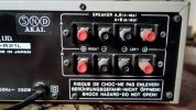
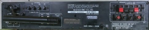
  • The difference in back panel layout should have been a dead giveaway. Here's a photo of the R21 backside, from Reclaimed Audio:
R21_back.jpg

Compared to my photos of the L in the opening post, certainly the antenna and mount are different. That may or may not turn me around enough when I need to get into the innards?

For now, simple cleaning though. Not dismantling anything beyond top and bottom plates to get out the accrued filth.
 
Does anybody know what the L signifies
long wave.

as you noticed, it has 3 tuning bands. fm, medium wave(am) and long wave(lw)

i do not know the unit but i would guess that the difference would be the tuner board. i would expect about everything else to be the same.

i've got an aa-r21. it's not a bad little unit.

i think the service manual you have should do you fine unless you plan on aligning the tuner for long wave


he frequency dial on the front panel drives a mechanical wheel setup connected with string
yes. analog tuner with a frequency counter.
 
@painttoad Thanks for clearing the L model name up. That makes sense.
I've seen other makes use the model number extension "E" for Europe, but I couldn't imagine this was a rare, regional model only for... Latvia, I guess?

unless you plan on aligning the tuner for long wave
Yeah, no. I never used the tuner part before, don't reckon I will now. I will try to restore it as close to original as I can, but realistically, I don't see that feature get much use anyway.
 
Removed the bottom plate as well, and gave the receiver a good dusting. Emptied a can of compressed air into all corners I could reach, and dusted the more persistent parts with a soft paintbrush.

Here's a before and after of bottom board components:
2025-12-02-08-32-04-543.jpg2025-12-02-09-04-32-316.jpg

And a couple of shots of the morning's work:
2025-12-02-09-05-31-775.jpg
2025-12-02-09-05-24-647.jpg

Also, bottom boards:2025-12-02-09-04-58-224.jpg
2025-12-02-09-04-40-369.jpg

Mind, those still need a good IPA wash, but I feel better hooking this to power than before...
 
The face plate and knobs came off as well, and have had a good scrubdown with wet wipes. Same treatment on the back panel speaker and input connectors. Those RCA plugs really shine again!

It's all in fairly good condition underneath the grime, apart from that antenna which I'll worry about later. The next challenge was high in my list from the beginning — cleaning the crud and crackle out of the potentiometers.

Why did 1980s manufacturers hate their customers so much that they hid potentiometers' maintenance ports (the holes where you de-ox it) way into the hardest accessible cranny? It was a hassle on my '85 Technics amp as well, but worse here.

The bass and treble pots I can maybe get to with a flexible straw on the spray can. There's wiggle room under the input selector LED meter board, I guess —

2025-12-02-10-18-09-269.jpg

— but the ones for balance and volume? Forget about it! They're so deep below the "counter" (ie, front display panel) PCB, I can't even get a clear picture to share.

2025-12-02-10-00-24-318.jpg

No really, they're in there, way at the back.

The counter PCB seems to be held only by a pair of screws, but really is lodged in by a mass of sturdy, soldered and secured wires. It's not budging.

I tried unscrewing the entire half of the bottom board to get at the pot meters, but of course that is secured to the frame all over.

Which leaves me with the front part of the frame. It seems possible to screw it loose, but I have no clue if it will help me here — or if it's the same deal with rigid cabling and other attachments :dunno:

@painttoad, you said you have the R21. How did you manage to clean your potentiometers?
 
Last edited:
Why did 1980s manufacturers hate their customers so much that they hid potentiometers' maintenance ports (the holes where you de-ox it) way into the hardest accessible cranny?

Meanwhile, on the front panel right next to each potentiometer pivot:

IMG_20251202_141717_1.jpg

:crazy: Nothing to see here, carry on (and apols @painttoad for calling you back in).
 
Well, shoot. Gave the AA-R21 service manual a look, and it looks like there are enough dissimilarity between that and my L model that the schematics won't translate 1:1. So, if anybody has the AA-R21L owner's and service manual lying around...

Looks like the two models are fairly similar, just not identical. They probably share parts with different layouts. Enough to confuse a first timer like me, though.

  • The R21L has front switches for LW and MW where the R21 just has AM (in addition to the FM/phono/AUX switches on both).
  • The difference in back panel layout should have been a dead giveaway. Here's a photo of the R21 backside, from Reclaimed Audio:
View attachment 3645721

Compared to my photos of the L in the opening post, certainly the antenna and mount are different. That may or may not turn me around enough when I need to get into the innards?

For now, simple cleaning though. Not dismantling anything beyond top and bottom plates to get out the accrued filth.

Have a look though the manuals in our AK Database. If you don't find what you need there, then you'll want to post a manual request in our Digital Docs forum.

 
Meanwhile, on the front panel right next to each potentiometer pivot:
potentiometers have a little keyway that prevents the body from spinning when turned and not soldered to a pcb. that hole is where the keyway rests


How did you manage to clean your potentiometers?
i do not know if i removed them or left them in the unit for a spray & pray. considering that i do not have a more broken down pic, i do not think that i removed them.


lil akai 055.jpg
 
I managed to access and spray the volume pot as well, but after that I had to reassemble the receiver and clear the work table for another (non-audio) project.

The sound still isn't very clear, the bass sounds like a whoopee cushion, and every turn of the volume knob makes the balance go off :dunno: I think the old girl needs a complete disassembly and checkup if I'm going to get it to work.

Good thing I don't rely on this for my everyday listening! I'll update here again when exams are over and I have time for the big audio autopsy.
 
I've finally gotten back to this project the past week. I'm still at a visual inspection, and trying to take this old thing apart so I can get her working again. I'll say again, this is a learning experience for me, and I have a lot to learn.

I'm focused on the power amp board, because last I tested with an input and headphones, there were loads of distortion (see above post). The receiver part doesn't worry me too much, but it does share a board with the eq. That's for next step, though.

For now, my challenges are—

Glued-down capacitors
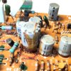
A handful of caps have been secured to the top of the board with glue, and Akai didn't skimp on that back then. Or perhaps it's the handiwork of a former owner? It's splashed on very enthusiastically, if nothing else.

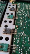
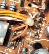
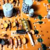
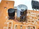
The glue has flowed on to nearby component pins, and especially where it touches transistors it has gone dark, hard and frail. In one case the adjacent transistor looks like it shorted, definitely something fried, and the board was a bit of a burnt, crusty mess around there.

I've removed both the capacitor and the transistor — at least the latter needs replacing, and I suppose the former, too. It is 45 years old, after all.

Considering the age, would it be preferable to just recap it all the way through? Either way, is it safe to get rid of the old glue that hasn't dried out?

PCB wire connector blocks
You'll forgive me for not knowing what else to call those:

IMG_20260519_214703.jpg
IMG_20260519_214836.jpg

Those bundles of wire hold the power amp board in place almost as much as the screws I removed... I mean to disconnect the wires to get the PCB out of the frame and work on it. But I'm not keen on having to remount them with the wire looping around those pins. That looks like a job I'd fast make a mess of.

So what happens if instead I desolder them from the other side of the board? Do they come off as one block, or will the pins come out individually?

Thanks in advance, will be happy to provide more info if I can.
 
Beautiful work on the restoration of that Akai! Tracking down dead transistors and bringing these classic silver-face units back to life is incredibly rewarding.

The only heartbreaking part of restoring these classic tuners nowadays is that modern local AM/FM broadcasting is mostly compressed garbage or corporate ad loops. A lot of collectors who finish an aesthetic restoration like this are now bypassing the dead local airwaves entirely by converting the old tuner or aux section into a global streaming hub.

Instead of ruining the rack with a clunky external Bluetooth adapter, you can actually mount a standalone internet radio diy kit inside the cabinet. If you look around for a dedicated internet radio diy kit, they make modules designed exactly for this kind of vintage overhaul. These boards come with a dedicated R-GND-L stereo analog audio output connector right on the deck. You can wire it directly to the stock Akai Aux or Tuner switch lugs using high-quality shielded cable. That way, you get modern uncompressed access to over 30,000 global stations directly through the amplifier's original volume and tone circuitry, keeping the glorious analog soul completely alive.
 
@Sam_Whatart Now, that does sound interesting. I never considered making the receiver digital-ready. Will have to look into that once I've gone over the power amp PCB :)
 
@Haverholm Totally agree, take your time with that power amp stage first! Dealing with that notorious 80s "corrosive glue" and those ancient wire-wrap pins is a true rite of passage.

Regarding those wire blocks: desoldering the pins from the back of the PCB as a single unit is usually much safer than trying to unwrap the wires from the top. The old copper strands are very brittle after 45 years and break easily if you try to bend them back.

Whenever you get that power board recapped and you're ready to look into the digital streaming side, just drop me a message. Don't waste time on standard compressed Bluetooth dongles—they will just become a bottleneck for that beautiful Akai tone stage you’re working so hard to restore.

Get those exams sorted first, and looking forward to seeing this classic beast roar again!

Cheers,Sam
 
@Sam_Whatart Good stuff, Sam! I appreciate your comments and advice. I'm learning as I go, and I'm careful not to do too much damage in the process. This receiver has a lot of affectional value to me.

I've gotten fairly good at soldering the past year, but looking into wire wrapping I sort of fell in love with the technique :D I almost (but only almost) regret that I don't have to learn that as well. But to keep things simple for myself, I'll take your advice and desolder the blocks instead ;)
 
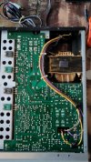
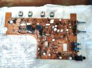
Got the wire wrap pins loose, and the board is out! Still some cleaning to do, I went over this with IPA and a toothbrush after most of those snapshots were taken:

IMG_20260527_134458.jpg

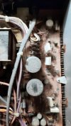
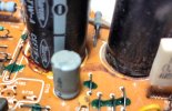
As I said before, somebody went a little crazy with the glue when these caps were mounted. It goes under, over, all the way around neighbouring components and the board in between. Not everything is as bad, but it's pretty clear the glue didn't take well to some 40 years next to a hot transistor:

IMG_20260527_134534.jpg
IMG_20260527_134612.jpg

^^ Can't wait until I have to change one of those resistors that has been gunked in with several other parts...

The green lacquer splotches are probably just anti-tamper factory seals? They don't bother me, I won't bother them. Some front panel screws had them too, they came loose with no issues.

IMG_20260527_134659.jpg

Just pour it in there, better safe than sorry!
Once again, where the glue flowed onto the transistor pins it's seared and hardened. Some of it was removed before the above was taken.

IMG_20260527_134735.jpg

The two big caps I may just leave although the glue seems a bit burnt? I suppose those build up a good deal of heat in themselves.

Ah, and finally a proper shot of where the fried transistor scorched the board, along with another glob of glue. I think this may be as clean as it gets with only IPA. Do you think it's a lost cause to work more on this, or is there a better solvent for burn marks?

IMG_20260527_134825.jpg
 
Last update for a while as I clear the work table for some non-electronics tasks. But I'll need some advice before I put in orders for spares:

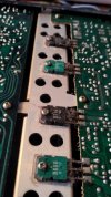
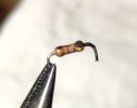
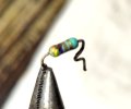
These two resistors were also singed in the transistor burn shown in my previous post:IMG_20260608_213744.jpgIMG_20260608_213722.jpg

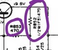
As far as I can tell from the colour bands (yellow-purple-brown) they're both 470 Ohm ±5%. But according to the schematic the turquoise-bodied one (R852) is a "fail safe resistor".

IMG_20260608_220113_1.jpg

As I'm new to this, please enlighten me — is "fail safe" just a function on the PCB, or is this a type that I'd need to search out under another name?
 
Back
Top Bottom