• The move to the new server is done. There are some software and database maintenance updates in process. This has us passing the hat around to help out. We appreciate any donations. Seriously, even a dollar helps. The payment page may be found here - https://www.audiokarma.org/support.html

Akai M-7 monoblocks

Jim Kiriakis

Active Member
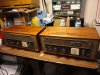
Recently acquired Akai R2R Terecorder. Arrived intact, I read threads on re-purposing / restoring. Removed the amps from their case along with the reel to reel. The military grey green color is compelling, and I like the quality. Cast faceplates, solid wood (mahogany?) case. Will likely cut the case in half, re-use the bottom to house the amps and take the top half robbing the stainless front plate of the reel to reel to use as a new scratch build amp chassis. Removed the EF86 NEC drivers (all the tube look to be original NEC) and the 6AR5, locked the switches into record mode, cleaned the innards and outside with large cotton swabs and high test isopropyl. Made up speaker wires on 1/4" jacks and ordered some 1/4" to female RCA adaptors. Checked coupling caps for leakage with EL84's out (after re-using the original power cord and fuse holder and moving the PT inputs from 100V to the 117V lugs). VU lamps illuminate though one meter is dead and the other has a cracked front surround bezel. Amps worked! Volume pots are scratchy but DeOxit helped tons. I've ordered new coupling caps and the 375pf caps to flatten the response (per another thread on this forum).
 

Attachments

  • M7.jpg
    M7.jpg
    147 KB · Views: 184
Last edited:
Register to hide this ad
You and at least one other unnamed audiokarma member...
A friend of mine, yeah...
A case of: "no specific plan but can't leave tube equipment at goodwill"

I am compelled to rescue this stuff when the price is reasonable (cheap) which means I have too much on my shelves.
 
Symptoms - left monoblock hums, doesn't play nearly at the volume relative to the right side amp through the "phono-radio" low gain input.

Running signal through the high gain "mic" input, amp will play but variable crackling seemingly related to the volume pot.

Any insights on how to diagnose? I've already changed out the .02 cap connected to the volume pot (C9) to the driver grid, and .01 uf coupling cap back to the power tube.
 
@grindfix you have many options.

I resolved the hum in the left monoblock. Cut out the PG1 four pin connector. With that substantial improvement (also fixed the gain issue), subbed in two NOS 5751 drivers and Funkwerk EL84s.
 
I got this pair from a member here a long while ago. My initial thought was to apply common mods that are published on this forum but after brief reading, it appears that running them in "record" mode alters the frequency response, and output is no longer flat, but "boosted". Is it true? I didn't spend enough time reading to fully understand that and left it for another day after I'm done with other started projects. Of course, that never ends...
I personally don't like the look of them as they are and if I were to use them as monoblocks, I'd rebuild them in the new chassis for a more aesthetically pleasing appearance. Than. this raises the question of whether to build them using the original "record mode" schematic or start from scratch and just use transformers. If those amps have their fame for the results of the circuit and not the transformers' quality, I probably just better pass them on to someone who will enjoy them in their original form. So, really not sure what to do with them yet.
 
... this raises the question of whether to build them using the original "record mode" schematic or start from scratch and just use transformers. If those amps have their fame for the results of the circuit and not the transformers' quality, I probably just better pass them on to someone who will enjoy them in their original form.

I built mine on a separate chassis and scrapped all the original circuitry. The only components I reused are the output and power transformers, and the PS chokes. The circuit is a modified version of the classic Mullard 3W. I changed the tube complement to EF86 - 6V6 and 6X5 rectifiers. Also differing from the Mullard, I used more conventional values to bias the EF86 and added a coupling cap between stages. The output transformers are much better than they have a right to be, especially considering their lowly tape deck origins. I included a few dB of global NFB to improve distortion and flatten frequency response at 20 kHz. I also experimented with various output tubes at the time, including the 1626, 6L6 and others. I feel the 6BQ5 has a slight edge over the 6V6 for dynamics, but both tubes are excellent in this application. As for sound quality, this has been my primary living room amp for more than 10 years. I'll eventually replace it with something more powerful, but the sonics are so incredibly transparent, and it drives my Grado phones with more nuance and detail than I've ever heard. It will always be a part of the system for at least that use.

Jack
 
this raises the question of whether to build them using the original "record mode" schematic or start from scratch and just use transformers. If those amps have their fame for the results of the circuit and not the transformers' quality, I probably just better pass them on to someone who will enjoy them in their original form. So, really not sure what to do with them yet.


Akai M8 modifications as stand-alone amps was my first valve amp project. I was not satisfied with the "locking in record mode" performance, although the output transformers are very good quality. I have moved these to the projects rack and shall rebuild them, have narrowed down two options for that. One is this
https://audiokarma.org/forums/index.php?threads/akai-m8-circuit-cut-down.460792/

Check @dcgillespie's posts on that page. Second option is again Dave's. His Magnavox 8600 improvement schematic can be implemented after ripping out the original. There is no need to replace the output transformers as advised in that topic because these Akai OPTs are very good.

Regards,
 
I just want to add that my early experiments with my M8 project included listening sessions comparing the EF86 to the 12AX7. The EF86 was immediately the winner in terms of subjective sound quality. In retrospect, the gain of the EF86 also seems to be the most suitable, falling in-between that of a single section or two cascade sections of the 12AX7. The EF86 is the more linear of the two types, and its potential for microphonics (sometimes noted by guitar players) is not an issue whatsoever at line level. Also note that a line level conversion of these amps does not require hum pots. It's worthwhile studying the simplicity of the Mullard 3W design before getting too far into the conversion.

Mullard 3W.jpg

Jack
 
In retrospect, the gain of the EF86 also seems to be the most suitable, falling in-between that of a single section or two cascade sections of the 12AX7.

Jack

I have looked at the Mullard circuit a few times. The input sensitivity is quoted at 100 mv. Won't that make the amp too sensitive for modern sources? Typical CD player output levels are around 1vrms. Just want to understand as a layman.

Regards,

Anwesh
 
I don't know the model number for Roberts deck my amps came out of. Are all transformers the same between all Akai and Roberts units?
 
I have looked at the Mullard circuit a few times. The input sensitivity is quoted at 100 mv. Won't that make the amp too sensitive for modern sources?

Mine has a dual 100K volume pot at the input. It's always between 9:00 o'clock and 3:00 o'clock, so the gain has proven to be perfect for my particular system. Of course, preamp gain also plays a role in this. In the end, excess gain is not an issue as long as it doesn't degrade signal-to-noise.

Jack
 
I don't know the model number for Roberts deck my amps came out of. Are all transformers the same between all Akai and Roberts units?
I performed warranty service on both brands back in the day. The Roberts decks were made by Akai, and I never saw any differences in the components inside the amplifiers. The Akai M6, M7 and M8 also share the same transformers, the only exception being primary taps to accommodate different line voltages.

Jack
 
Exactly why I don't want to do it in a "record lock" mode. I have built one amplifier using Dave's SE Maggie schematic and I'm happy with the results. Since this is a monoblock set, I think I want to do it differently. Jack's suggestion locks my interest, I want to keep EL84 tubes. I have a ton of those and none of the new 6V6 tubes.
I have 3 unfinished (kind of finished) units to finish before starting a new project but I'm certainly more intrigued now than I was a few days ago. ;)
 
Per Dave Gillespie's post #11 in this thread: https://audiokarma.org/forums/index.php?threads/akai-m8-circuit-cut-down.460792/

I implemented his network resections between the driver and power tubes, reapplied feedback, and omitted driver cathode cap C30. Still need to delete the 8ohm OT protective load resistor. Left and right amps are sounding better.

One interesting and perhaps unsurprising observation: on the caps that have been removed, I have measured capacitance with a digital multimeter. In every case, they've drifted well out of spec, = 20 - 40% and beyond. For fun I harvested the Nippon Chemi Con1 mfd 300V which was part of the R2R, and it measured over 2 mfd.
 
I dissected the amp today and drafted a formal schematic. Some of the non-critical values are the result of parts I had on hand. You can change those to more traditional values without problems. For example, the 510K resistor at the grid of V2 could be 470K. Also bear in mind that I built this quite a few years ago. I'll be glad to answer questions, but I might not remember the basis for every component selection.

6V6-SEP-Amp.jpg

Jack
 
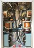
Here's a pic of the inside layout. The front panel is at the top. The pilot lamp, power/speaker switch, volume control and phone jack are mounted left to right in that order.


6V6 amp inside sm.JPG
 
Back
Top Bottom