• The move to the new server is done. There are some software and database maintenance updates in process. This has us passing the hat around to help out. We appreciate any donations. Seriously, even a dollar helps. The payment page may be found here - https://www.audiokarma.org/support.html

ALK Universal Economy Crossover for the Heresy

You might just want google the subject. It would require a lot of writing to explain it in a way that gives it justice.

Also, Al’s networks are diplexers. The impedance of the low pass and high pass are matched to create a “constant impedance”. It’s not really possible to cancel out the rising impedance of the woofer - so you work around it. The ALK presents a relatively benign load to the amp.
 
AE049584-A8D0-44A9-9EBF-14DDCD1111D3.gif 994C34F0-62FC-4AD1-8098-355257F9B7C6.jpeg
You might just want google the subject. It would require a lot of writing to explain it in a way that gives it justice.

Also, Al’s networks are diplexers. The impedance of the low pass and high pass are matched to create a “constant impedance”. It’s not really possible to cancel out the rising impedance of the woofer - so you work around it. The ALK presents a relatively benign load to the amp.
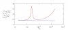
You can cancel out the rising impedance woofer peak with a Zobel Network, but typically it is not necessary. With the right filter, you can get the blue flat line vs red.
 
Last edited:
Yes. Al tried that with his networks and had an issue with it. I think it related to back EMF, but to be honest I just can’t be sure. Too many years!
 
I guess I'm mostly trying to understand what benefit there is, if any, to running a higher order network on a speaker that is already phase and time compliant with relatively low intermodulation, unless you're using drivers that are wildly out of spec.
 
Some peope prefer lower order networks because they allow the drivers pass band to overlap more. Lower order networks "sound" different than higher order networks. Higher order networks have been said to sound more sterile and clinical, but they also allow the drivers to handle more power if you need that attribute.

IMO, the universal crossover allows each driver to do what is does best and sounds excellent, but then others like the modified Type E.
 
I guess I'm mostly trying to understand what benefit there is, if any, to running a higher order network on a speaker that is already phase and time compliant with relatively low intermodulation, unless you're using drivers that are wildly out of spec.

Out of spec drivers are not the issue with crossover order; 1st order/6dB, 2nd order/12dB, 3rd order/18dB, 4th order/24dB, etc.

In a very general sense, if you have wide bandwidth drivers and they can handle moderate to high power, you can probably use a 1st order/6dB type crossover and have good sonic results from the speaker system.

In a lot of cases, you use different crossover topologies in the same crossover network like the "universal". The woofer section of the universal is 6dB low pass, the midrange section has a 6dB high pass & 12dB low pass, the tweeter is an 18dB high pass.

Low(er) order crossovers also save money. Crossover components can easily add up very quickly adding significantly to the manufacturing cost of a speaker system.

Again, in a very general sense, if a speaker has good performance over a limited bandwidth, you can use a higher order crossover to utilize the bandwidth area of importance and filter out the anomalies.

One advantage of the "universal crossover" is the fact that it has an almost constant impedance across the audio band (except for the main woofer driver resonant peak) because I use a lot of SE amps with no feedback and it helps tremendously to have a flat impedance curve with these type amps.

 
Could you explain that to me as If I built my first crossover in the past 6 months?
Let's take a K-55 driver nominal impedance of 16 ohms. When you use the T2a Autofomer, as you drop each tap, you double whatever the impedance of your driver might be. So for 4, 3, 2, 1, it's 2x, 4x, 8X, 16X multiplication. So on the number 3 tap, it's 4X16 Ohms=64 ohms. The higher the impedance, the smaller the Capacitor required for a given crossover point. Each time you drop the number one spot Down on the T2a, you have to cut your capacitance in Half. Using a swamping resistor keeps the impedance constant, so the capacitor can stay the same. From ALK website:

If something could be done to stabilize the impedance seen by the filter when a transformer tap was moved, the level to the squawker driver could be adjusted without disturbing the filter. Enter the swamping resistor! Rather than design the squawker filter to work into the 32 Ohm load reflected through the autoformer when set to the 3 dB tap. Lets design it for the 8 Ohm level most amplifiers want to have as a load. Recall that resistors in parallel total up as 1 / (1/R1 + 1/ R2). What value of resistor could we connect in parallel with the 32 Ohms looking into the autoformer to bring the total down to 8 Ohms? The value turns out to be about 10 Ohms. 1 / (1/32 + 1/10) = 7.6 Ohms. We can connect it right across the 0 and 5 taps of the transformer. Now, if we move the transformer tap all the way down to the 15 dB setting, where the turns ratio becomes 5.62, the impedance ratio becomes 31.6, or the square of the turns ratio. The 16 Ohm load now looks like 506 Ohms (31.6 X 16) looking into the transformer. Using the parallel resistance formula again the filter sees 1 / (1/10 + 1/ 506) = 9.8 Ohms. Any 8 Ohm system would be happy with that load! The impedance seen by the filter can’t go higher than 10 Ohms even with no load at all! The 10 Ohm resistor swamps out the inductance of the driver in the same way as the resistive part of the drivers impedance. In addition, a speaker driver is a linear electric motor which generates “back-emf” as it moves. This voltage sees the 10 Ohm resistor on the other side of the transformer as a much LOWER impedance because the transformer now is stepping the impedance down rather than up in the exact same way. This improves the damping factor to the driver. A resistive L-Pad attenuator can not do this! The 10 Ohm resistor forms a parallel circuit which does not add attenuation to the driver. It simply draws extra current from your amp. The extra power it draws is not going to raise your electric bill even slightly! Your amp will see the 8 ohms it was designed to see, not 32 Ohms like it sees with the stock Klipsch crossover networks. The swamping resistor is a win-win situation and has no down side.
 
After all this, PWK proved that the Higher Impedance of the Heresy E network REDUCES Intermodulation Distortion in amplifiers better than an 8 ohm resistor load. I suspect he would not agree with using the ALK method, but who knows. He's been RIP for almost 21 years now.
 
Last edited:
Your amp will see the 8 ohms it was designed to see, not 32 Ohms like it sees with the stock Klipsch crossover networks. The swamping resistor is a win-win situation and has no down side.

After all this, PWK proved that the Higher Impedance of the Heresy E network REDUCES Intermodulation Distortion in amplifiers better than an 8 ohm resistor load. I suspect he would not agree with using the ALK method.

thanks. I understand it less poorly now. What are your thoughts on the ALK Method? Also, are there easy to read primers on crossover design and implementation that are accessible to the lay hobbyist? I understand crossover networks better than I did 6 months ago, but I can't say that I understand crossover networks.
 
TIM was a big deal when many solid state amps were still trying to get their footing. The Otala tests were late 60’s.

It’s a good sounding network.
 
TIM was a big deal when many solid state amps were still trying to get their footing. The Otala tests were late 60’s.

It’s a good sounding network.
Transient Intermodulation Distortion (TIM) is not really an issue with modern amps, regardless of topology (tube, solid state, digital Class D). For early transistor designs though, there was a big learning curve and it took awhile for designers to learn how to design and develop stable designs with early slow BJT's. Slew Induced Distortion was also a big concern because a lot of early amps did not have the needed bandwidth at high(er) powers.
 
We all saluted the work of Dr. Matti Otala of Finland, including PWK, who said it should be called "Otala Distortion." I'm not sure which amp he used for the test, but it was defending his use of Autoformers for horn attenuation, of which, the Heresy was the most popular and most Horn Attenuated candidate. It was in one of the "Dopes from Hope" long ago and it stuck with me.
 
Friend, after a extensive research, I'm very prone do follow your way and build your crossover. Tks for posting and explain so good! One question, what wire gauge for the 2.5mH solid iron core? And 0.20mH / 0.30mH Litz?
Here is my version of the "universal" that has yielded excellent results. You can massage the cap values to your liking; such as 26uf instead of 28.2uF.
 
Friend, after a extensive research, I'm very prone do follow your way and build your crossover. Tks for posting and explain so good! One question, what wire gauge for the 2.5mH solid iron core? And 0.20mH / 0.30mH Litz?
2.5mH - iron core, 18AWG, DCR < 0.3 ohms
0.2mH - air core, 20AWG, DCR < 0.3 ohms
0.3mH - air core, 20AWG, DCR < 0.4 ohms

I don't use Litz, but you can. Litz is not worth the extra money for me and I can get excellent results with "normal" iron and air coils.
 
TIM aside, an autoformer alone will reduce insertion loss. Standard numbers are -

6dB = 5%
12dB = 10%
18dB = 15%
24dB = 20%

You get some of that back when you don’t turn watts into heat.
Yepper. And the MAIN reason everyone uses Cheap Resistors instead of Autoformers is COST, Cost, cost. Always follow the MONEY as the Answer to Everything...........including Government bull$hit.
 
2.5mH - iron core, 18AWG, DCR < 0.3 ohms
0.2mH - air core, 20AWG, DCR < 0.3 ohms
0.3mH - air core, 20AWG, DCR < 0.4 ohms

I don't use Litz, but you can. Litz is not worth the extra money for me and I can get excellent results with "normal" iron and air coils.
I'm so glad to receive your answer! Yes, money and cost is a very important question, even more here in Brazil, where they heavily tax international purchases.
 
Yepper. And the MAIN reason everyone uses Cheap Resistors instead of Autoformers is COST, Cost, cost. Always follow the MONEY as the Answer to Everything...........including Government bull$hit.
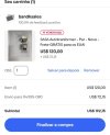
Example... 192 USD + 60% minimun Brasil import tax 115USD, total 307.
307 USD to BR Real 307x5 = 1535 BRL

Hera a 12 step wall attenuator is 505 BRL.
Is my only option.

1000127616.jpg1000127615.jpg
 
Back
Top Bottom