

You are using an out of date browser. It may not display this or other websites correctly.
You should upgrade or use an alternative browser.
You should upgrade or use an alternative browser.
Allied 333/Pioneer sx34 - minimum work required
- Thread starter P. S.
- Start date
-
- Tags
- allied 333 pioneer sx34 recap

So I am slowly getting up to speed on this project.
The caps have arrived but I figured out some of them have too short leads. I am talking especially the caps in the power section. I need to order some wire to lengthen them. The biggest voltage I see in these caps is 250V.
I consider a couple of wiring options:
- regular copper solid romex wire 12AWG which I have at home (probably not a good option - but I would be able to fit it in right away ;-)
- I have some old speaker crossover wires I can pull out and use them (concerned about voltage though).
- order 20AWG/600V solid or stranded wire from Mouser.
As a total lame in the world of tube amps - I still have more questions with regard to wire (hope you can bear with me):
- should I go with 20AWG or maybe use 18AWG (bigger wire = less heat)
- Does voltage rating mean anything (i.e. is 600V rated wire better than 300V rated)
- I see lots of cheap wire on Amazon - wondering if that's worth buying or maybe just go for mouser (supposedly - better quality)
- which type of wire do you find better to work with - stranded or solid?
Sorry for lame questions but most of my soldering experience is with swapping out caps from PCB boards. Have not done much restoration where all caps are wired.
Regards,
-Peter
The caps have arrived but I figured out some of them have too short leads. I am talking especially the caps in the power section. I need to order some wire to lengthen them. The biggest voltage I see in these caps is 250V.
I consider a couple of wiring options:
- regular copper solid romex wire 12AWG which I have at home (probably not a good option - but I would be able to fit it in right away ;-)
- I have some old speaker crossover wires I can pull out and use them (concerned about voltage though).
- order 20AWG/600V solid or stranded wire from Mouser.
As a total lame in the world of tube amps - I still have more questions with regard to wire (hope you can bear with me):
- should I go with 20AWG or maybe use 18AWG (bigger wire = less heat)
- Does voltage rating mean anything (i.e. is 600V rated wire better than 300V rated)
- I see lots of cheap wire on Amazon - wondering if that's worth buying or maybe just go for mouser (supposedly - better quality)
- which type of wire do you find better to work with - stranded or solid?
Sorry for lame questions but most of my soldering experience is with swapping out caps from PCB boards. Have not done much restoration where all caps are wired.
Regards,
-Peter

Tim D
Super Member
I use cut leads from other caps and resistors to extend the ones that are too short. I'll give them a slight twist and solder them with a reasonable overlap, then I cover the splice with shrinkwrap in part to hide the splice.
In terms of the 600V wire, I use that on the high voltage wiring - usually associated with B+ or something derived from B+ with high voltage (i.e. screen grids, etc.) I also look for teflon coated wires as they hold up very well to the heat from soldering irons and daily use in hot amps. The challenge is to find solid wires in the gauge you want. It always seems that there are more choices in stranded wires with the 600V rating. I like to get a color assortment. I have found some choices on the big retail site. In fact I used a color assortment of 20awg stranded wire on a recent project and it worked out ok, but with stranded the wire dressing doesn't turn out so nice as it does with solid wire. (Note that IMHO, you could probably get by with 300V wire, but given the choice I go with 600V just to have that safety margin. If you go with the lower voltage then there is a bit more risk of the insulation breaking down under high voltage. I've never heard of anyone having trouble, but who knows?)
In terms of the 600V wire, I use that on the high voltage wiring - usually associated with B+ or something derived from B+ with high voltage (i.e. screen grids, etc.) I also look for teflon coated wires as they hold up very well to the heat from soldering irons and daily use in hot amps. The challenge is to find solid wires in the gauge you want. It always seems that there are more choices in stranded wires with the 600V rating. I like to get a color assortment. I have found some choices on the big retail site. In fact I used a color assortment of 20awg stranded wire on a recent project and it worked out ok, but with stranded the wire dressing doesn't turn out so nice as it does with solid wire. (Note that IMHO, you could probably get by with 300V wire, but given the choice I go with 600V just to have that safety margin. If you go with the lower voltage then there is a bit more risk of the insulation breaking down under high voltage. I've never heard of anyone having trouble, but who knows?)
Last edited:

Jazzbow
Super Member
Just a little FYI: the J.J. Electronics caps are only rated at 70°C. Probably sufficient but for a couple of dollars more I use the F&T caps. They're rated for 85°C anyway. I figure if O.E.M. caps were 85° then that should be fine. With my Bogen I'm going with the CE Manufacturing from AES since they also carry the F&T. There's just not enough room under the hood for individual caps here.
Tim D
Super Member
I always try to get 105C or better caps due to the heat that comes with Tube units. It gives me that peace-of-mind, but maybe that's just me. In fact I almost got a set of caps at 145C recently but the order went to backordered, so I cancelled them and went with something I had on hand.
Jazzbow
Super Member
I always try to get 105C or better caps due to the heat that comes with Tube units. It gives me that peace-of-mind, but maybe that's just me. In fact I almost got a set of caps at 145C recently but the order went to backordered, so I cancelled them and went with something I had on hand.
I understand wanting that safety margin. 85°C is about 185° F. At that temperature your equipment is already in trouble. Not trying to be argumentative: Hayseed Hamfest uses 105° caps in their twistlocks and they're a few dollars cheaper than the comparable CE units. I just have a hard time paying $35 knowing what's inside is $4 worth of radial caps. The other option is rebuilding the caps yourself. A lot of people talk about how much of a PITA it is but I've done at least 20 and only had one hard one. I re-stuff them with the Nichicon "pencil" caps from Mouser. They're 105°C low ESR caps.

The brown caps are fine and you don’t need to replace them. Some of these receivers got the brown caps and some of them got the gray oil caps. I am guessing one of them was an earlier version and the other was a later version. I have had some of one and some of the other. The brown film capacitors work extremely well and test almost perfect now. No worries with them.
I found some 18awg stranded wire coming I cut out from the ceiling fan I installed a few months back. (it really pays of to stash stuff sometimes!) It's rated 600V 105C. Made the leads for 2 filter caps last night. It looks ugly but should work good enough. Planning to swap all the rest of caps during the next few days. Will post photos once I finish.
The brown caps are staying. Only electrolytics go away. I also plan to leave multi-caps in place for now until I learn more how to replace them with many individual caps.
All caps will be 105C rated - paid special attention to it when I was ordering them as the unit gets really hot ;-)
The brown caps are staying. Only electrolytics go away. I also plan to leave multi-caps in place for now until I learn more how to replace them with many individual caps.
All caps will be 105C rated - paid special attention to it when I was ordering them as the unit gets really hot ;-)

mhardy6647
Lunatic Member
The perfect is the enemy of the good.

Jazzbow
Super Member
I save wire from flourescant lamps whenever I have to change a ballast. 18awg solid 600v 105c wire. Bit thicker than I absolutely need but free is good for me.
Back in '08 I replaced ballasts in about 60 fluorescent fixtures and kept all of the trimmings. Great wire: as has already been said, solid is easier to use and results in neater lead dress.
So I finally got to recap.
The attached photo shows the final result. The 18awg stranded wire worked fine for my purpose to extend the leads on the big filter caps. The soldering job does not look great - but at least it works.
For now I recapped only the bottom part of the receiver (total 8 caps) and left the multi-caps as is. Need to learn more how to replace them yet. After recap I gradually brought it up on the variac to 115V. All tubes lit up, no hum even at maximum volume. Sound is great but more detailed/crisp in highs and bottom is more tight than before recap. I used nichicon caps. All my solid state receivers where I used nichicons have this sound signature for the 1st couple of weeks. Then it mellows out. Heard some people use Elna for more mellow sound.
One beginner tip I learned the hard way is to take 3 photos of each cap before cutting it out. I figured it is very easy to lose track where the leads should go after the original cap is taken out. I ended up doing photos where I would show with the screwdriver where leads go + one photo to capture polarization. After I finished the recap I was grateful to people who invented PCB-s ;-)
Now I just need to swap out the backlight bulbs for the radio scale and polish the faceplate. Maybe learn how to bias the tubes and do it as well.. Tightening up tube sockets would be the next good step also as some come out really easily.
All tubes are still original Matsushitas. Wondering what would be good replacement to start tube rolling etc.
But for now I guess I am just going to finish cleaning and detailing and do some listening ;-)
I am grateful to everybody in this thread who helped me doing a 1st tube amp restoration. That's 1st tube amp in my collection and it works as a result of your help and knowledge!!! ;-)
Thank you, you are great!
-Peter
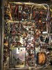
The attached photo shows the final result. The 18awg stranded wire worked fine for my purpose to extend the leads on the big filter caps. The soldering job does not look great - but at least it works.
For now I recapped only the bottom part of the receiver (total 8 caps) and left the multi-caps as is. Need to learn more how to replace them yet. After recap I gradually brought it up on the variac to 115V. All tubes lit up, no hum even at maximum volume. Sound is great but more detailed/crisp in highs and bottom is more tight than before recap. I used nichicon caps. All my solid state receivers where I used nichicons have this sound signature for the 1st couple of weeks. Then it mellows out. Heard some people use Elna for more mellow sound.
One beginner tip I learned the hard way is to take 3 photos of each cap before cutting it out. I figured it is very easy to lose track where the leads should go after the original cap is taken out. I ended up doing photos where I would show with the screwdriver where leads go + one photo to capture polarization. After I finished the recap I was grateful to people who invented PCB-s ;-)
Now I just need to swap out the backlight bulbs for the radio scale and polish the faceplate. Maybe learn how to bias the tubes and do it as well.. Tightening up tube sockets would be the next good step also as some come out really easily.
All tubes are still original Matsushitas. Wondering what would be good replacement to start tube rolling etc.
But for now I guess I am just going to finish cleaning and detailing and do some listening ;-)
I am grateful to everybody in this thread who helped me doing a 1st tube amp restoration. That's 1st tube amp in my collection and it works as a result of your help and knowledge!!! ;-)
Thank you, you are great!
-Peter
So actually after a few days looks like the unit is going to get back on the bench. Looking from the front at the top - the left multi-section cap is getting very hot. Not burning hot that I cannot touch it but it's super warm.
Plan is to recheck the voltages and inspect the power supply. Then - if needed - replace the cap with 3 independent caps.
Plan is to recheck the voltages and inspect the power supply. Then - if needed - replace the cap with 3 independent caps.

Did some more poking around and found that the multi section caps seem to be actually running cold but the cage-like metal section right next to them gets super hot and radiates heat onto them!.(marked on the photo). Quite hard to see whats behind the metal grid or take it apart but i see some brown cigar like objects which seem to be 8w/400ohm resistors to me (r79, r80)? The metal grid gets super hot a few min after power on. Then it slowly heats up the can caps.
since the resistors are in this metal sort-ofa-shield its probably ok for them to get hot? Not sure though
Decided to replace the can caps anyway. Will post update in a few days.
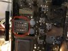
since the resistors are in this metal sort-ofa-shield its probably ok for them to get hot? Not sure though
Decided to replace the can caps anyway. Will post update in a few days.
Tim D
Super Member
P.S.
I'm waiting to hear if anyone that has one that is working will comment as to whether that is normal or not.
To me it doesn't seem normal at all for that level of heat. In looking at the schematic those two resistors (R79 and R80) are dropping resistors in the power supply for the various B+ draws. Yes, those usually take heat, but they should be sized appropriately to avoid excessive heat and stress. The fact that it has a cage around them makes me believe that they might have had a design problem with them and needed to provide some barrier to protect the surrounding components. The first thing I would do is to measure the voltages at those resistors and compare them against the voltages on the schematic. If everything measures normally then I'd be uprating the power handling on those resistors significantly. (Maybe parallel two 7W or 10W 800 ohm resistors to get you the 400 ohms to replace each. Of course they need to fit inside that box too.)
Looks like you would need to get inside that box to investigate further. Do you feel you are up to the task? Can you work with high voltages safely? If not then you should find someone that can. Good luck.
I'm waiting to hear if anyone that has one that is working will comment as to whether that is normal or not.
To me it doesn't seem normal at all for that level of heat. In looking at the schematic those two resistors (R79 and R80) are dropping resistors in the power supply for the various B+ draws. Yes, those usually take heat, but they should be sized appropriately to avoid excessive heat and stress. The fact that it has a cage around them makes me believe that they might have had a design problem with them and needed to provide some barrier to protect the surrounding components. The first thing I would do is to measure the voltages at those resistors and compare them against the voltages on the schematic. If everything measures normally then I'd be uprating the power handling on those resistors significantly. (Maybe parallel two 7W or 10W 800 ohm resistors to get you the 400 ohms to replace each. Of course they need to fit inside that box too.)
Looks like you would need to get inside that box to investigate further. Do you feel you are up to the task? Can you work with high voltages safely? If not then you should find someone that can. Good luck.