You are using an out of date browser. It may not display this or other websites correctly.
You should upgrade or use an alternative browser.
You should upgrade or use an alternative browser.
Almost finished a Receiver repair, then disaster strikes. What to do?
- Thread starter Donguri
- Start date
-
- Tags
- crackle hk 450 pulsating dbt

elnaldo
Lunatic Member
If polarity is right, I don't see any problem with that.One thing to mention:
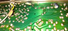
I put the new C19 / C20 caps on the underside of the Pcb since the C19 was hard to access from the top.
Don't know if this is ok to do or not or if it had anything to do with the failure.
View attachment 3329273

If the input caps being pulled makes it quit acting stupid, its probably something upstream of that. Maybe stick a voltmeter from ground to the output of the preamp and see if its bouncing around. Analog is easier to see, or a scope, but even a digital might show you something. If the signal coming out of the preamp is goofy, the amplifier is simply going to amplify the goofiness and make it draw power when it tries.
Low voltages would be explained by a dim bulb tester, but they should be equal voltage on the + and -. Try a larger bulb and see if it evens out.
Low voltages would be explained by a dim bulb tester, but they should be equal voltage on the + and -. Try a larger bulb and see if it evens out.
Thanks, so in this case Preamp Output would be from ground to C515 / C516?Maybe stick a voltmeter from ground to the output of the preamp
Will try the bigger bulb as well.
Would this mean you are thinking that the culprit may be in the - rail and not + rail?It seems something is pulling the voltage down
I did some measurements at Preamps Transistors (with the 40W bulb) but the strange thing is that the discrepancy doesn't show up..
I know for sure some of the Tr´s must be bad since of the popcorn sound, but they still measures ok?
The Voltage discrepancy does show up at D17 / D18 and R10 / R11 before the C13 and C12 if that tells you anything?
Or maybe those are just effected from something in the Pre amp as well?
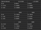
Upgraded the Bulb to 60W
C12 (+B5 rail) now measures: 14.40V dead on
C13 (-B5 rail) now measures: 12.28 - 12.33V
With DMM:
Ground to + side of C516 jumps around in mV
Ground to + side of C515 jumps around from -mV to + 1-2V and 4-5V on the - side of the cap, so clearly something is wrong in the R-CH.
Ground to input caps on the Preamp
C508: -103mV
C507: 000.1mV
C12 (+B5 rail) now measures: 14.40V dead on
C13 (-B5 rail) now measures: 12.28 - 12.33V
With DMM:
Ground to + side of C516 jumps around in mV
Ground to + side of C515 jumps around from -mV to + 1-2V and 4-5V on the - side of the cap, so clearly something is wrong in the R-CH.
Ground to input caps on the Preamp
C508: -103mV
C507: 000.1mV
elnaldo
Lunatic Member
Hello. With a DBT, specially if it's a bit bright, the voltages will be off by some margin. I see B5 rails are regulated by Zener diodes, if you have a low voltage reaching the Zener, they won "regulate". They need to drop some Volts to work.
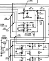
Please check (with the unit unplugged and capacitors discharged), resistance to ground from B5 rails, to see if you have a low resistance in some rail (indicating a shorted component ahead), and check the dropping resistors R8, 10 , 11, 13. All those resistors limit the current and drop some Volts when the circuit is working OK. If you don't find anything obvious, you could measure the voltage drop across those resistors and see if some of them is getting too hot or dropping too much voltage, indicating a large current draw ahead.
Check also B1 and B2, they should match if both channels are working the same way. B5 rails are fed by B1 rails, so a problem at B1, dropping the voltage, will make B5 to be lower too.
Removing R10 and R11 will interrupt the power to +B5 and -B5, not powering the preamp section. (just in case you need to diagnose just the power amp).
B4 feeds the Phono preamp. Removing R8 will interrupt only that rail.
Please check (with the unit unplugged and capacitors discharged), resistance to ground from B5 rails, to see if you have a low resistance in some rail (indicating a shorted component ahead), and check the dropping resistors R8, 10 , 11, 13. All those resistors limit the current and drop some Volts when the circuit is working OK. If you don't find anything obvious, you could measure the voltage drop across those resistors and see if some of them is getting too hot or dropping too much voltage, indicating a large current draw ahead.
Check also B1 and B2, they should match if both channels are working the same way. B5 rails are fed by B1 rails, so a problem at B1, dropping the voltage, will make B5 to be lower too.
Removing R10 and R11 will interrupt the power to +B5 and -B5, not powering the preamp section. (just in case you need to diagnose just the power amp).
B4 feeds the Phono preamp. Removing R8 will interrupt only that rail.
Ground to + side of C515 jumps around from -mV to + 1-2V and 4-5V on the - side of the cap, so clearly something is wrong in the R-CH.
yeah thats your pulse in DBT with the preamp connected to the power amp. The amplifier is just amplifying what its being fed. No pulsing input to the power amp = no pulsing current load.
What it is I don't know but since it seems like there isn't anything goofy going in to the preamp, you're looking at something between the input and the output. I will say the 100-odd mv is strange, I'd expect basically zero there so it may be that the transistor is leaky.
There really isn't a ton to the preamp, input is a differential pair formed from Q501 / Q503, and the output is from Q505's collector. Tone controls are a feedback circuit between the collector of Q505 and the base of Q503. (and of course their equivalents on the other channel). The only two shared components appear to be C19 and C20, which are power supply decoupling caps. Since both channels aren't being stupid we can probably rule those out. I suppose if one of the other caps in the right channel were backwards it could cause dumbness. Basically not a whole lot that can go wrong here. If the caps are in right, maybe pull the transistors and check them.
Excellent couple of advices, much appreciated, will get on all of it tonight and get back.Please check (with the unit unplugged and capacitors discharged), resistance to ground from B5 rails
Aha, yes that does make sense, Thank you, learning a lot here.yeah thats your pulse in DBT with the preamp connected to the power amp.
Thought so too.. But are you thinking that those, perhaps leaky, transistors are located in the Left ch?I will say the 100-odd mv is strange
Or would a couple of leaky transistors in the Right ch be able to "spill over" to the Left ch?
I did replace the 2SC1344´s in Q501/ 503 and Q502/504 with the recommended KSC1845F and the unit was running fine until the bang..
Could it be that since this unit is a "High Current" unit that the KSC1845F are not a sufficient replacement in the preamp?
I'll double check the Caps polarity.

elnaldo
Lunatic Member
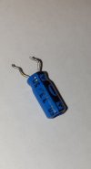
I wouldn't worry about the capacitors leakage by now. The problem you have i not related to the capacitor leakage.
A low leakage capacitor is always a good thing in an audio circuit, but don worry about that by now you have a real problem to fix.
You can measure the capacitor leakage out of circuit, connecting a high value (let's sat 100Kohm) resistor in series with the capacitor, applying a voltage to the capacitor, and measuring the voltage drop across the resistor. You won have "laboratory accuracy", but it's a good test to compare different capacitors.
A larger resistor will give you more accurate results, more mV under a low current flow. A smalle resistor won't show a significant voltage if the current is too small.
I forgot to mention since post #1: You replaced transistors and capacitors, and then you had a problem just in one channel. I'd double check again, with a mag glass, everything you did and you don't trust 100%. Anything you suspect it was not perfect, hard to reach points, a broken pcb trace, something you had doubts when doing it, and so. In cases like your, usually the problem is a human mistake. But you know better than us what things you did and you don't trust 100%.
A low leakage capacitor is always a good thing in an audio circuit, but don worry about that by now you have a real problem to fix.
You can measure the capacitor leakage out of circuit, connecting a high value (let's sat 100Kohm) resistor in series with the capacitor, applying a voltage to the capacitor, and measuring the voltage drop across the resistor. You won have "laboratory accuracy", but it's a good test to compare different capacitors.
A larger resistor will give you more accurate results, more mV under a low current flow. A smalle resistor won't show a significant voltage if the current is too small.
I forgot to mention since post #1: You replaced transistors and capacitors, and then you had a problem just in one channel. I'd double check again, with a mag glass, everything you did and you don't trust 100%. Anything you suspect it was not perfect, hard to reach points, a broken pcb trace, something you had doubts when doing it, and so. In cases like your, usually the problem is a human mistake. But you know better than us what things you did and you don't trust 100%.
elnaldo
Lunatic Member
I did replace the 2SC1344´s in Q501/ 503 and Q502/504 with the recommended KSC1845F and the unit was running fine until the bang..
Could it be that since this unit is a "High Current" unit that the KSC1845F are not a sufficient replacement in the preamp?
I've reand here in AK that in some situations, the 50mA if the KSC1845 vs the 100mA of the original transistor, could be a problem, but only if the transistor is pushed to it's limits, feeding some very high level signal. If in doubt, replace them and fit the original parts again.
Thanks for walking me through this, I'll disregard the caps for now.In cases like your, usually the problem is a human mistake
I did repair a lift trace at the C510 but that was in the Left CH and the serious problem is in the R CH so disregarded it.
Might revisit that trace again as well.
I've read the same thing but I've also seen videos of *edit* competent techs using this same transistor in same position on this unit so thought they were OK.I've reand here in AK that in some situations, the 50mA if the KSC1845 vs the 100mA
Unfortunately two of the old ones were bad and produced the popcorn/frying bacon sound
Last edited:
Going to dive in to the unit today but will just post the requested results of the testing points if anyone has any input:
C12 2.070 Mohm (is this what to expect?)
R10 490 ohm (SM 470 ohm)
R11 395 ohm (SM 390 ohm)
R13 2.160Kohm! (SM 120 ohm) but it is connected to a cap, is this resulting in higher ohm?
R10 +14.39V / +20.78V
R11 -12.44 / -20.60V
R13 -14.74V / -20.68V
I´ve noticed that -B2 cap holds 21V charge for long time but the others drops to around a volt after turning the unit off.
C13 0.820 Mohm (I wasn't clear if one should expect high resistance in a healthy rail?)resistance to ground from B5 rails, to see if you have a low resistance in some rail
C12 2.070 Mohm (is this what to expect?)
R8 403 ohm (SM 390 ohm)check the dropping resistors R8, 10 , 11, 13.
R10 490 ohm (SM 470 ohm)
R11 395 ohm (SM 390 ohm)
R13 2.160Kohm! (SM 120 ohm) but it is connected to a cap, is this resulting in higher ohm?
R8 +14.74V / +21.06Vmeasure the voltage drop across those resistors
R10 +14.39V / +20.78V
R11 -12.44 / -20.60V
R13 -14.74V / -20.68V
they all measured kind of the same, 24V + or - 10 mVCheck also B1 and B2,
I´ve noticed that -B2 cap holds 21V charge for long time but the others drops to around a volt after turning the unit off.
elnaldo
Lunatic Member
R 13 is probably open. Nothing in parallel with a resistor can increase the total resistance. I'd double check that. Desolder it if needed.
Voltages make sense, but if r13 is open, something is wrong. Narrow your search around R13 and the associated zener and caps
A Capacitor holding the charge means the circuit is not drawing current. Some open circuit. That could mean something, together with the other symptoms.
Voltages make sense, but if r13 is open, something is wrong. Narrow your search around R13 and the associated zener and caps
A Capacitor holding the charge means the circuit is not drawing current. Some open circuit. That could mean something, together with the other symptoms.
Got it, Will do.Narrow your search around R13 and the associated zener and caps
Btw, Really want to understand so would you mind to clarify this regarding the resistance in the Rails?
C13 0.820 Mohm (I wasn't clear if one should expect high resistance in a healthy rail?)
C12 2.070 Mohm (is this what to expect?)
Very much appreciated!Large resistance, in those magnitudes, are not relevant.
Will use this in future troubleshooting.
Made a misstake, measured at R18 and not R13, confused 3 and 8 on the schematic.
Caps polarity in pre amp checks out.
Reflowed almost all my previous soldering and it seems like the jumping voltage has stopped, now only fluctuating a couple milivolts +/- at C515/C516.
But the about 100mV present everywhere where it should be 0 is still there.
B5 Rail voltage discrepancy is still there.
Will pull the Q501/503 Transistors tomorrow.
Reflowed almost all my previous soldering and it seems like the jumping voltage has stopped, now only fluctuating a couple milivolts +/- at C515/C516.
But the about 100mV present everywhere where it should be 0 is still there.
B5 Rail voltage discrepancy is still there.
Will pull the Q501/503 Transistors tomorrow.
Pulled the Q501 / Q503, they didn't measure bad, but I've read that Transistor tester doesn't reveal noisy transistors so changed them for a new pair.maybe pull the transistors and check them.
But same results, small -95 to -145mV on all test points in the pre amp that should be Zero...
Voltage discrepancy still there but I think I've might have found something thanks to this advice:
Checked voltages backwards at C14 / C15 and they were uneven as well, so measured connecting R12 / R13 ohm and voltage drop (@ a 40W bulb)Narrow your search around R13
R12 121.8 ohm 18.72V / 16.57V
R13 126.4 ohm -18.70V / -15.50V
Could R13 be the culprit for the Voltage discrepancy at B5 rails??
?