

You are using an out of date browser. It may not display this or other websites correctly.
You should upgrade or use an alternative browser.
You should upgrade or use an alternative browser.


jaaronb
Active Member
I'm pretty sure it needs to be significantly reduced in value, if not removed altogether.
Please post pics............... we love pics!
Thanks Bowtie - I'll absolutely post pics tomorrow night when I get back into town. That 20ohm resistor has always been a question mark for me... you'll see in the pics I post, but I've cartoonishly followed the N-800F schematic... I'd rather it be right than pretty.
jaaronb
Active Member
I used some small needle nose pliers to remove mine
That said, any oxidation of the screen changes it's acoustic characteristics from the original spec, and that's not a good thing.
Thanks for this input gents.
Elitopus, when you say you used needle nose pliers to remove them, does that mean you reached through the hole to simply grab them after separating them from the horns... Or did you have to further disassemble the drivers to get at the screens?

elitopus
Addicted Member
Thanks for this input gents.
Elitopus, when you say you used needle nose pliers to remove them, does that mean you reached through the hole to simply grab them after separating them from the horns... Or did you have to further disassemble the drivers to get at the screens?
Correct, I removed the driver from the horn and pulled out the screen with pliers. I use a little pull and turn action to make sure the screen comes out of the groove without ripping.
It takes about two minutes to do both drivers once they are free from the horns.

twiiii
Lunatic Member
An Altec Carmel with two 414's, 811 and 806 placed appropriately could reach 35 hz quite easily. but the bass wasn't clean like a Bozak Symphony. The Carmels harmonic distortion was horrible and why I never kept mine. As you have a later version of the woofers that distortion issue may be much lower. I could get a flat response with a 4 cu ft ported enclosure with one 414 woofer with no trouble. So I imagine a 8 cuff enclosure not ported located properly in the room would give the best results. Use 2 inch insulation all around the inside of the enclosure and hang a 2 in curtain directly behind the magnets. The combination will be better damped and have a smoother roll off. Placed in a room properly you should be able to reach 30 Hz, but you will loose a few db of efficiency. I would use a N1201 crossover to keep the horn under control and not sounding like a honker. Plus you can adjust the highs separately from the mid range. With a modern diaphragm the combination of horn, driver. and crossover ought to be able to handle over twice to three times the power using a 800 Hz crossover with original diaphragm.
jaaronb
Active Member
Correct, I removed the driver from the horn and pulled out the screen with pliers. I use a little pull and turn action to make sure the screen comes out of the groove without ripping.
It takes about two minutes to do both drivers once they are free from the horns.
Thanks for this - I wonder if our drivers aren't configured differently. Were the screens on your drivers mounted on the outer surface of the magnet body, i.e., exposed when you separated the horn from driver?
I was doing some research last night and I think I know why I was having a hard time understanding this operation... The screens on my 806a are located on the inner end of the cylindrical magnet, i.e., inside the driver. So when I separate the horn from the compression driver, there's no screen on the outer surface of the magnet... The screens are mounted flush against the inner wall of the magnet...~4" away from the visible outer surface of the magnet, accessible only through the ~1" diameter x 4" long cylindrical cavity of the driver.
Were your screens positioned this way? I'd think the risk of debris falling into the driver body would high if one were to reach through the magnet body with needle nose pliers, grasp the screens at the center and pull...
elitopus
Addicted Member
Thanks for this - I wonder if our drivers aren't configured differently. Were the screens on your drivers mounted on the outer surface of the magnet body, i.e., exposed when you separated the horn from driver?
I was doing some research last night and I think I know why I was having a hard time understanding this operation... The screens on my 806a are located on the inner end of the cylindrical magnet, i.e., inside the driver. So when I separate the horn from the compression driver, there's no screen on the outer surface of the magnet... The screens are mounted flush against the inner wall of the magnet...~4" away from the visible outer surface of the magnet, accessible only through the ~1" diameter x 4" long cylindrical cavity of the driver.
Were your screens positioned this way? I'd think the risk of debris falling into the driver body would high if one were to reach through the magnet body with needle nose pliers, grasp the screens at the center and pull...
Yes the screens are mounted like you said, within the body. I took some long, small needle nose pliers and reached in there and grabbed the screen. I held the driver above my head so the debris would fall out and not into the phase plug.
If you are worried about debris you could always takes out the diaphragm and then clean the gap/phase plug area afterwards.
I also have some Emilar drivers which have the screen on the mounting gasket. Now THOSE are easy to descreen

jaaronb
Active Member
Yes the screens are mounted like you said, within the body. I took some long, small needle nose pliers and reached in there and grabbed the screen. I held the driver above my head so the debris would fall out and not into the phase plug.
If you are worried about debris you could always takes out the diaphragm and then clean the gap/phase plug area afterwards.
I also have some Emilar drivers which have the screen on the mounting gasket. Now THOSE are easy to descreen
Awesome! Thanks so much for the reply elitopus! Feel much better about this operation now!
jaaronb
Active Member
Please post pics............... we love pics!
Meant to get around to posting crossover pics yesterday, but wasn't able to get to it. I'll get some up asap today!

Here are a few pics of my project so far... Hoping to finish in the next week or so.
Boxes and baffles are stained here, but not yet finished - planning too use Waterlox to finish them.
View attachment 897268 View attachment 897269 View attachment 897271
DANG son, that's mighty fine work!!!
jaaronb
Active Member
Thank you! I appreciate the kind words! Still have a ways to go!DANG son, that's mighty fine work!!!
jaaronb
Active Member
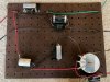
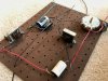
Ok...finally got a chance to post a couple pics of the crossovers. This is just a mockup - I'll run wires underneath and tie everything down before soldering - I've run wires up top and spaced things out a lot to make any mistakes visible. Top section is LF (green/black), bottom section HF (red/brown).
The cap/resistor on the bottom right are values Zilch suggested as a starting for about 3db of fixed additional compensation into a 16ohm load.
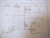
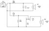
I used the original n-800f schematic, which matches up with one Zilch and others mapped out.
I already know they're uglier than dirty sin, but I'd greatly appreciate anyone taking a look and flagging any mistakes I've made or changes I should make. I know there are more elegant ways to do this...but I'm on training wheels here.
Thanks again to everyone who's chimed in. Feel like I'm closing in on it.
The cap/resistor on the bottom right are values Zilch suggested as a starting for about 3db of fixed additional compensation into a 16ohm load.
I used the original n-800f schematic, which matches up with one Zilch and others mapped out.
I already know they're uglier than dirty sin, but I'd greatly appreciate anyone taking a look and flagging any mistakes I've made or changes I should make. I know there are more elegant ways to do this...but I'm on training wheels here.
Thanks again to everyone who's chimed in. Feel like I'm closing in on it.
Attachments
jaaronb
Active Member
Are you saying I did them right...or good?The xovers are looking good. I like how you spaced the components, especially the inductors.
jaaronb
Active Member
Are you saying I did them right...or good?
What I mean I is... Does it look like I did it right?
elitopus
Addicted Member
You left some nice space between the coils like you are supposed to. The layout looks clean.
Honestly if it works electrically, it doesn't really matter how it looks. Especially if its going inside the cab anyways.
My 604 crossovers look like a rats nest. They sound sweet though.
What caps/bypass caps are you using? Did you already post it and I missed it?
Honestly if it works electrically, it doesn't really matter how it looks. Especially if its going inside the cab anyways.
My 604 crossovers look like a rats nest. They sound sweet though.
What caps/bypass caps are you using? Did you already post it and I missed it?
jaaronb
Active Member
I don't think I posted the values, but they're what's called for in the N-800f schematic:
LF caps are Clarity Cap ESA 10uf, and Mundorf Supreme .47uf for the 10.5uf value.
The HF caps are Solen SB at 3.9uf.
I'm using a Solen PB cap at 6.2uf paralleled with a Mills 8 ohm resistor in series on the + HF side as a substitute for the adjustable 30923 attenuation circuit, which I may add later. I *think* the 6.2uf + 8ohm resistor is about equal to the L-Pad of the 30923 network being set at about half into a 16ohm load.
Thanks again for your help elitopus. I honestly don't care so much about the looks either.
Having never made anything from a schematic before, I was hoping if I did anything in error here, it would be apparent.
I (visually) made a literal copy of the N-800F schematic layout, which I know isn't electrically necessary for it to work - hoping nothing I've done precludes proper function.
I did omit the 20ohm resistor after the L-Pad at Bowtie's suggestion, as I believe the true L-Pads I'm using fulfill its function in the original quasi-L-Pad pot + resistor Altec used originally.
Remains to be seen whether these work electronically! I should have these up and running in the next few days, so if anything looks off here, hopefully someone will notice.
My only question on these is whether I've wired the inductors properly in the circuit in terms of 'in' and 'out'. I believe I have.
Assuming these work well, I'll probably look to change all the caps out to Mundorfs eventually.
LF caps are Clarity Cap ESA 10uf, and Mundorf Supreme .47uf for the 10.5uf value.
The HF caps are Solen SB at 3.9uf.
I'm using a Solen PB cap at 6.2uf paralleled with a Mills 8 ohm resistor in series on the + HF side as a substitute for the adjustable 30923 attenuation circuit, which I may add later. I *think* the 6.2uf + 8ohm resistor is about equal to the L-Pad of the 30923 network being set at about half into a 16ohm load.
Thanks again for your help elitopus. I honestly don't care so much about the looks either.
Having never made anything from a schematic before, I was hoping if I did anything in error here, it would be apparent.
I (visually) made a literal copy of the N-800F schematic layout, which I know isn't electrically necessary for it to work - hoping nothing I've done precludes proper function.
I did omit the 20ohm resistor after the L-Pad at Bowtie's suggestion, as I believe the true L-Pads I'm using fulfill its function in the original quasi-L-Pad pot + resistor Altec used originally.
Remains to be seen whether these work electronically! I should have these up and running in the next few days, so if anything looks off here, hopefully someone will notice.
My only question on these is whether I've wired the inductors properly in the circuit in terms of 'in' and 'out'. I believe I have.
Assuming these work well, I'll probably look to change all the caps out to Mundorfs eventually.
elitopus
Addicted Member
I think its easier to follow the schematic the way you laid it out. For something simple like this there is nothing wrong with that. You can do a quick visual check and make sure everything is correct.
Quick story. This avionics guy I worked with a couple years ago came into shop complaining about the schematic he was working off of. He said he couldn't get the wires to fit in the aircraft the way the schematic showed. When we asked him to show us he said he couldn't get all those bends like they showed on the schematic. We had a good laugh and explained the difference between a routing drawing a schematic
You will know if you wired it correctly when you hook it up. I always hook up the woofer first. That way if I got my connections crossed I don't send low frequencies to the horn and fry the diaphragm.
Quick story. This avionics guy I worked with a couple years ago came into shop complaining about the schematic he was working off of. He said he couldn't get the wires to fit in the aircraft the way the schematic showed. When we asked him to show us he said he couldn't get all those bends like they showed on the schematic. We had a good laugh and explained the difference between a routing drawing a schematic
You will know if you wired it correctly when you hook it up. I always hook up the woofer first. That way if I got my connections crossed I don't send low frequencies to the horn and fry the diaphragm.
jaaronb
Active Member
Well... I'm closing in on it. I did some rudimentary bracing on the cabinets - glued/screwed 2x2s on all interior surfaces. Baffles are now installed and the first coat of finish applied. All that remains is a few more coats of finish on the enclosures, replace the fiberglass damping (gonna staple some Uhaul felt-type moving blankets over top on the fiberglass), solder crossovers and wire them up. More pics to come...
bowtie427ss
Lunatic Member
Networks look good, lightly solder one up and give it a working test being sure to proceed with caution, in other words don't try to twist the volume knob off until you are sure you are connected properly and all is working as it should.
IMO, the U-haul blankets are prohibitively thick and will be too acoustically reflective making the combination of those on top of the fiberglass and effective reduction of cabinet volume at many frequencies.
I assume your goal is to capture/trap any loose glass fibers. If that's the case, get some cheesecloth from the hardware store, dye it black(or any color you like) and staple that over the fiberglass, you can double it up if you feel the weave is too open on a single layer. This will serve to trap most any loose glass fibers and retain most of the wide range acoustic performance of the fiberglass.
IMO, the U-haul blankets are prohibitively thick and will be too acoustically reflective making the combination of those on top of the fiberglass and effective reduction of cabinet volume at many frequencies.
I assume your goal is to capture/trap any loose glass fibers. If that's the case, get some cheesecloth from the hardware store, dye it black(or any color you like) and staple that over the fiberglass, you can double it up if you feel the weave is too open on a single layer. This will serve to trap most any loose glass fibers and retain most of the wide range acoustic performance of the fiberglass.